
You are using an out of date browser. It may not display this or other websites correctly.
You should upgrade or use an alternative browser.
You should upgrade or use an alternative browser.
LED lighting
- Thread starter wayles3
- Start date
ModelRailroadForums.com is a free Model Railroad Discussion Forum and photo gallery. We cover all scales and sizes of model railroads. Online since 2002, it's one of the oldest and largest model railroad forums on the web. Whether you're a master model railroader or just getting started, you'll find something of interest here.


")
Plus so much easier for folks without electrical knowledge to understand, without having to explain a "common" type wiring system to them.
Then another big one, I realized that resistors are costing less than .01 each. At that "price" why I don't have to worry about and analyze the exact circuit. I can just use one resistor for each LED.

Affiliate Disclosure: We may receive a commision from some of the links and ads shown on this website (Learn More Here)
Iron Horseman
Well-Known Member
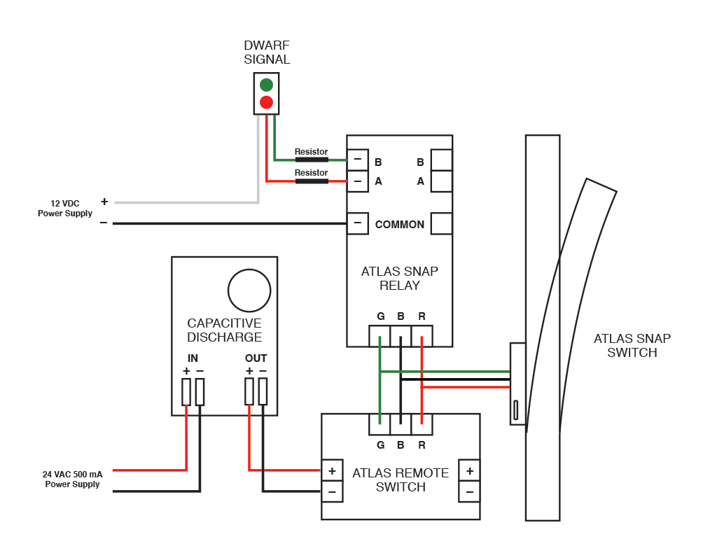
Sure there is, that is kind of its whole purpose in life. It is just a relay. You need a power supply for the red and green lights and connect it to one of the the relay outputs. If you choose LEDs for lighting you will need a resistor for each. There are many diagrams for it on-line. Search for "Atlas Snap Relay 200 Instructions".
Example: And, No, you don't need the capacitive discharge. it is just and example.
Example: And, No, you don't need the capacitive discharge. it is just and example.
Smudge617
Well-Known Member
Am I missing something here, I've at least 14 ground (dwarf) signals, all wired up to 12v and working, is there a particular aspect of the Atlas snap switch that needs resistors on both negative LED lines, I only use one, on the positive, I'm aware it doesn't matter where on the circuit you place the resistor, but why use two when one will do?Sure there is, that is kind of its whole purpose in life. It is just a relay. You need a power supply for the red and green lights and connect it to one of the the relay outputs. If you choose LEDs for lighting you will need a resistor for each. There are many diagrams for it on-line. Search for "Atlas Snap Relay 200 Instructions".
Example: And, No, you don't need the capacitive discharge. it is just and example.
One resistor on the common lead will work as will a resistor on each of the negative leads . The only time it will make a difference is if the LED's are both on at the same time . I'm using a single LED that is red/green . The red is a lot brighter than the green . I used a higher value resistor on the red wire so it is now the same intensity as the green portion.Am I missing something here, I've at least 14 ground (dwarf) signals, all wired up to 12v and working, is there a particular aspect of the Atlas snap switch that needs resistors on both negative LED lines, I only use one, on the positive, I'm aware it doesn't matter where on the circuit you place the resistor, but why use two when one will do?
Smudge617
Well-Known Member
Now it senseOne resistor on the common lead will work as will a resistor on each of the negative leads . The only time it will make a difference is if the LED's are both on at the same time . I'm using a single LED that is red/green . The red is a lot brighter than the green . I used a higher value resistor on the red wire so it is now the same intensity as the green portion.
Iron Horseman
Well-Known Member
Not missing anything. As you note and the other poster stated it can work just fine. I used to use a single resistors. Then I when was using them for hot frog indication I noted that a single common resistor could allow both LEDs to light in certain circumstances. When I switched to one-per they went back to what I considered "normal", both LEDs not lighted in that same circumstance.Am I missing something here, I've at least 14 ground (dwarf) signals, all wired up to 12v and working, is there a particular aspect of the Atlas snap switch that needs resistors on both negative LED lines, I only use one, on the positive, I'm aware it doesn't matter where on the circuit you place the resistor, but why use two when one will do?
Plus so much easier for folks without electrical knowledge to understand, without having to explain a "common" type wiring system to them.
Then another big one, I realized that resistors are costing less than .01 each. At that "price" why I don't have to worry about and analyze the exact circuit. I can just use one resistor for each LED.
Smudge617
Well-Known Member
Yeah, that makes senseNot missing anything. As you note and the other poster stated it can work just fine. I used to use a single resistors. Then I when was using them for hot frog indication I noted that a single common resistor could allow both LEDs to light in certain circumstances. When I switched to one-per they went back to what I considered "normal", both LEDs not lighted in that same circumstance.
Plus so much easier for folks without electrical knowledge to understand, without having to explain a "common" type wiring system to them.
Then another big one, I realized that resistors are costing less than .01 each. At that "price" why I don't have to worry about and analyze the exact circuit. I can just use one resistor for each LED.
Just one thing though... you said detection. There is no track occupancy detection with this, only switch position indication. You can add a dwarf so there are two facing the points, connect the red/green in opposition (by wiring them in parallel), so the through track is green and the other is red. On the points end, it will always be a clear indication without any occupancy detection. But it's cheap and easy.
Affiliate Disclosure: We may receive a commision from some of the links and ads shown on this website (Learn More Here)