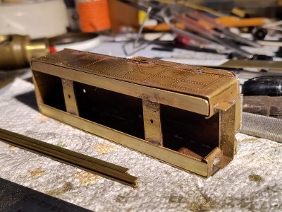
Kriegsloks building shops


Looking at the size of the boiler, it looks like you should be able to put a good sized motor and a good amount of weight in it too. I look forward to seeing photos and video when you complete it.
I've got this huge Maxon Swiss motor about 22mm in diameter. Unfortunately there is no space for a flywheel. I guess DCC will solve that. The boiler itself is huge and there's definitely a lot of space for weight in it.
 
It's most likely calculated best shape weight for the main and side rods on the opposite side of the wheel. Form follows function. If you look at any counter weights on steam locomotives, you'll see that they are not directly on the opposite side of side rod pins, but are a little offset. You can tell by where the edges of the counter weight is (inside edge of the crescent) as opposed to the spokes.
Great answer, thank you!
 
Today work, train show after that and i managed to squeeze an hour or more working on that L&NE decapod. After decomposing that old metal tender into pieces and trimming both ends shorter it was time to solder all together:
IMG_20241018_234840518.jpg
IMG_20241018_234834041.jpg

Here is the original frame with three axle trucks and shortened coal and water bunker.
IMG_20241018_234938249.jpg
Since the main frame has some cuts in it which were not present in the tenders of those F-1 steamers, i'll have to put together a new frame. That's it for today.
 
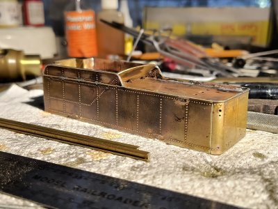
Continuing on the tender i decided to do the bead around the top edge since that adds a visual completness:
IMG_20241020_102910149.jpg
IMG_20241020_111948530.jpg

This wasn't actually too bad and it gives more texture to tender walls;
IMG_20241020_104608683.jpg

I also did the lower bead which runs bellow the very top one:
IMG_20241020_121749698_HDR.jpg

Next were the steps all the way around and ive had to scratch build the steps also since i didn't have the exact ones:
IMG_20241020_160910937.jpg
IMG_20241020_182313060_HDR.jpg

I also started doing the bottom plate which will be screwed into the tender and it will actually hold the trucks in place;
IMG_20241020_182242846.jpg
IMG_20241020_163553997_HDR.jpg
 

Attachments

  • IMG_20241020_130016056_HDR.jpg
    IMG_20241020_130016056_HDR.jpg
    541.1 KB · Views: 23
  • IMG_20241020_130029860_HDR.jpg
    IMG_20241020_130029860_HDR.jpg
    575 KB · Views: 21
More work on the tender today; i've built up the rear steps on the corners of buffer beam (my own method of thickening up the details-solder in a wire from behind and file to shape), hand rails, ladder, plugged the holes from old water hatch and put in new water hatch in the proper place and tail light;
IMG_20241021_224955361.jpg
IMG_20241021_225009859.jpg
IMG_20241021_224942359.jpg
IMG_20241021_224932081.jpg

Oh, and the smoke stack since this beast had a Bethehem booster for a rear truck.
 
Last edited:
Ah, I’ve been wondering about that, had to look it up! 😎
Yes Sir, not many modelers are familiar with these and even less are modeling them. The great John Allen who created the legendary "Gorre and Daphedid" had a few on his layout. There were basically two companies which offered them; Franklin and Bethlehem. Some companies like Delaware and Hudson even had three axle boosters under a few of their tenders.
5028.1702414481.jpg

This is the builders photo of a brand new F-1 taken at Baldwin, taken from the Internet https://images.app.goo.gl/RfxnkXWpcR9vYePL7
...and you can see that i made the stack on the tender too short🤣
 
Yes Sir, not many modelers are familiar with these and even less are modeling them. The great John Allen who created the legendary "Gorre and Daphedid" had a few on his layout. There were basically two companies which offered them; Franklin and Bethlehem. Some companies like Delaware and Hudson even had three axle boosters under a few of their tenders.View attachment 202283
This is the builders photo of a brand new F-1 taken at Baldwin, taken from the Internet https://images.app.goo.gl/RfxnkXWpcR9vYePL7
...and you can see that i made the stack on the tender too short🤣
You're doing a fantastic job on that F-1! I look forward to seeing it when you complete it. I believe John Allen had at least three booster trucks. Gorre & Daphetid 34 and 35 each had one, and I think 27 had one off and on, but I can't seem to find a photo of 27 with the booster fitted, so I'm not sure
Gorre& Daphetid (2).jpg
Screenshot (409).png
.
 
Some more work done on the tender during the week, specifically building up that rear beam and shaping it to install the coupler at proper height:
IMG_20241022_161846211.jpg
IMG_20241022_162007021_HDR.jpg
IMG_20241022_161813866_HDR.jpg
IMG_20241022_161823513_HDR.jpg

The locomotive itself sits a little uneven and i'll have to drop the back end down almost 1mm. I still have to build up the frame of the tender to actually mount both trucks in place. I have also extended that smoke stack on the tender to more proper height.
 
Today back on the locomotive itself and started to dress up the front of the smokebox and work on twin compressors with the shield. Still more details just on the front; bell, main hinges which i'll have to build from scratch, more piping on those compressors with associated oil filters right next to compressors...the whole compressor set up is just sitting loose on the deck for now.
IMG_20241026_210743052_HDR.jpg
IMG_20241026_210708682_HDR.jpg
IMG_20241026_210720610_HDR.jpg
IMG_20241026_210727358_HDR.jpg
IMG_20241026_195350131_HDR.jpg

Picture of the real 401 which is probably what i will number my model. One oil filter is visible right under the headlight, the other is hidden behind that closer set of steps to the walkway. Numbers 403 and 404 had the piping and oil filters set up differently, while number 402 was the same as 401. Since soldering the whole assembly to the deck is out of the question, i'll just build it up and make it to screw into the deck from underneath, this will also make it easier to paint when the time comes for that.
Overall portrait so far:
IMG_20241026_213300309.jpg
IMG_20241026_213320547.jpg
 
Last edited:
Today back on the locomotive itself and started to dress up the front of the smokebox and work on twin compressors with the shield. Still more details just on the front; bell, main hinges which i'll have to build from scratch, more piping on those compressors with associated oil filters right next to compressors...the whole compressor set up is just sitting loose on the deck for now.View attachment 202704View attachment 202705View attachment 202706View attachment 202707View attachment 202708
Picture of the real 401 which is probably what i will number my model. One oil filter is visible right under the headlight, the other is hidden behind that closer set of steps to the walkway. Numbers 403 and 404 had the piping and oil filters set up differently, while number 402 was the same as 401. Since soldering the whole assembly to the deck is out of the question, i'll just build it up and make it to screw into the deck from underneath, this will also make it easier to paint when the time comes for that.
Overall portrait so far:View attachment 202714View attachment 202715
Looks great! I'm really enjoying watching your progress on it.
 
I have noticed some steam locos have lots of exposed piping and some little or none.

Would you explain the purpose for the piping and why some steam engines have a whole series of pipes

Thank you in advance...
Oh crap😲!. I can explain some of it, but not all. On this particular model the piping is hard to figure out do to poor pictures available. The thing under the cab is the water injector. Locomotives always have two of them, one on each side. So there is a piping coming from the cab with steam to power up the injector and the steam propells the water from the injector toward the front of the boiler and you can barely see the valve hidden by the deck where water is shot into the boiler. Right above that valve is a sand box and the three pipes coming down from it are sand lines to throw sand under wheels when slipping or starting a heavy train. Sand box is that huge reservior behind the chimney. The three lines coming from under the cab and running just below the walkway (right side of the locomotive), are for the brake system. The main tank on the F-1 was on the left side of the locomotive:
5028.1702414481~2.jpg

That is the huge torpedo like tank just above the driving wheels. Secondary tank is located under the front of the smoke box:
IMG_20241026_210727358_HDR.jpg

You can just barely see it under the smoke box hidden behind the set of air compressors-those vertical things sitting behind the shields right in front of the smoke box. Air compressors were of course powered by steam and that adds more piping. On a model like that i can not reproduce all piping exaxtly because the boiler is screwed to the main frame and there's a need to separate assemblies. Getting back to that left side there you see more piping just above that main tank and it loooks like it goes back and forth, that's in order to cool the compressed air a little, sort of like a radiator, otherwise hot air would cause damage. Also on left side you see sand pipes coming down from sandbox just like on right side. Under the cab is the other injector with its associated piping; steam is released into injector and it pushes the water from tender into the boiler. Normally one injector is used and the other is used as a spare in case one fails. There is more piping on top of the boiler right in front of the cab, that device is the turret (sort of like distributor) and by turning nobs in the cab the steam from the boiler is used to power the devices i described. What i can't figure out are those two very thick pipes running forward from the turret and then turning diagonally to run under the walkway. They deffinitely run forward and i wonder if they power the compressors, all pictures are very dark in that area and i'll have to do more digging to figure out how they run under the walkway. This particular model will have another very thick pipe on the right side that will come from the boiler near where the cylinders are, that was a steam pipe to power the booster truck on the tender:
.trashed-1731540672-timthumb~2.jpg

On the picture above you can see that pipe starting just behind the cylinder block, running under the power reverser, making an "S" curve to run under the grate and then under cab, i didn't get to that pipe yet on my model. I hope that explains some of it a little. There is also a bunch of small piping at the front, on the side of the smoke box, i have no clue what that piping was for and the earlier F-1s; 401 and 402 didn't have that.
 
Oh crap😲!. I can explain some of it, but not all. On this particular model the piping is hard to figure out do to poor pictures available. The thing under the cab is the water injector. Locomotives always have two of them, one on each side. So there is a piping coming from the cab with steam to power up the injector and the steam propells the water from the injector toward the front of the boiler and you can barely see the valve hidden by the deck where water is shot into the boiler. Right above that valve is a sand box and the three pipes coming down from it are sand lines to throw sand under wheels when slipping or starting a heavy train. Sand box is that huge reservior behind the chimney. The three lines coming from under the cab and running just below the walkway (right side of the locomotive), are for the brake system. The main tank on the F-1 was on the left side of the locomotive:View attachment 203050
That is the huge torpedo like tank just above the driving wheels. Secondary tank is located under the front of the smoke box:View attachment 203051
You can just barely see it under the smoke box hidden behind the set of air compressors-those vertical things sitting behind the shields right in front of the smoke box. Air compressors were of course powered by steam and that adds more piping. On a model like that i can not reproduce all piping exaxtly because the boiler is screwed to the main frame and there's a need to separate assemblies. Getting back to that left side there you see more piping just above that main tank and it loooks like it goes back and forth, that's in order to cool the compressed air a little, sort of like a radiator, otherwise hot air would cause damage. Also on left side you see sand pipes coming down from sandbox just like on right side. Under the cab is the other injector with its associated piping; steam is released into injector and it pushes the water from tender into the boiler. Normally one injector is used and the other is used as a spare in case one fails. There is more piping on top of the boiler right in front of the cab, that device is the turret (sort of like distributor) and by turning nobs in the cab the steam from the boiler is used to power the devices i described. What i can't figure out are those two very thick pipes running forward from the turret and then turning diagonally to run under the walkway. They deffinitely run forward and i wonder if they power the compressors, all pictures are very dark in that area and i'll have to do more digging to figure out how they run under the walkway. This particular model will have another very thick pipe on the right side that will come from the boiler near where the cylinders are, that was a steam pipe to power the booster truck on the tender:View attachment 203052
On the picture above you can see that pipe starting just behind the cylinder block, running under the power reverser, making an "S" curve to run under the grate and then under cab, i didn't get to that pipe yet on my model. I hope that explains some of it a little. There is also a bunch of small piping at the front, on the side of the smoke box, i have no clue what that piping was for and the earlier F-1s; 401 and 402 didn't have that.
That is super helpful! The sand tubes were about all I could figure out on my own.

Thanks again!!!!!!!
Dave LASM
 
That is super helpful! The sand tubes were about all I could figure out on my own.

Thanks again!!!!!!!
Dave LASM
The piping on locomotives gets even more complicated when some models get different types of water heaters attached, like Elesco type. Elesco type was that cylindrical device either over the front top of the smokebox, or burried within the front of the smoke box. Either way it used steam to preheat water that was pumped from the water pumps. It then injected hot water into the boiler, making operation of steam locomotive more efficient. This Boston and Albany 2-8-4 is a good example: https://images.app.goo.gl/1TpPr8yuqcpjcnZNA
Taken from this site: https://images.app.goo.gl/NKYooKw2y9iYHGtV7
The cylindrical heater forms like a brow over the front of the smokebox and adds that menacing look to it. You can also see how much extra piping is reguired to operate it. Some railroads, like the Pennsy stayed away from it since the company chiefs preffered simplicity. New York Central on the other hand had many of their steam locomotives fitted with it. Other water heaters were used, like exhaust steam heaters as those on Western Marylands almost identical I2 decapods to my model.
There were Worthington water heaters which could be found on Pennsy I1 "Hippos":
20210124_094025.jpg

I'm learning about this stuff myself and it's fun sometimes just to be able to tell what railroad the particular steam locomotive was working on just by looking at the devices used, without looking at what it's written on the tender.
 
Last edited:
Today something a little different fell into my hands. It's a printed hood with frame and under frame details:
IMG_20241030_160322390.jpg
IMG_20241030_160348372.jpg

Only a few people have done a model of this electric locomotive, and no brass was ever offered by any Japanese or Korean builders. It is Electro-Motive Division of General Motors experimental GM6C, of which a single unit was build in 1975 and delivered to Penn Central electric zone for testing. At the time studdies were being done (again) for extending the catenary from Harrisburg, Pennsylvania across Allegheny mountains to Pittsburgh and Conway yard as the western limit. Someone else has done the design work for the printer and with a small fee i bought the download program and sent it to someone in my area who did the printing for me. Both the designer and the printer did a splendid job, as i just compared the locomotive to a drawing which was printed long time ago in July 1976 issue of Railroad Model Craftsman:
IMG_20241030_160333794.jpg

I actually started to kitbash this model out of Athearn SD40-2 back at the end of high school, but that project is in one of my boxes (waiting for better time🙈🙉🙊). I did however solder scale Faiveley pantographs for just such a project:
IMG_20241030_160652008.jpg
IMG_20241030_160701908.jpg
IMG_20241030_160646907.jpg

Fully operational even with upper stabilizer bar to keep the pantograph shoes horizontal when running off of catenary wire. Scaled Faiveleys are basically impossible to find, as no one makes them in that size for American electric locomotives. European versions of Faiveleys are much smaller since wires in Europe generally hang a little lower than in United States. The closest to find the right type of pantographs for this are Bachmann pans for their E60 electrics, i don't think they are full metal though. The earlier versions of Bachmann pantographs are fully plastic with only the lower stabilizer bar metal, only other option would be to find Walthers Faiveleys for their Metroliner MU, or early Bachmann Metroliner MU pantographs since they were made fully out of metal. The rack which the pantographs of Metroliners sit in, are different though and would need to be modified if someone is more hardcore into realism.
The designer of the printout wrote that the main frame is made to fit Kato trucks and motor for SD40-2. Real GM6C actually used same HT-C trucks as the SD40-2 with modified motors. So i might try the easier way and find a used Kato SD40-2, or modify the main frame i already have and use my Athearn drive to power the beast. Here is the pick of real GM6C:
7986809269_67d7758ce7_b.jpg

Grabbed quickly off Flicker. As can be seen the locomotive was painted all white with red tiger stripes on both noses and very dark blue (no, they were not black) GM ELECTRO-MOTIVE signs and sported number 1975 on cabs and number boards. Later probably sometime at the end of 1979, or early 1980 the number was changed to 4975 to keep it consistent with 4000 numbers in Conrail electric fleet. Just like the rest of the Conrail electric fleet, this unit was out of work when Conrail decided to shut down its electric operations in early 1981. GM6C was sent back to La Grange where it was built and eventually scrapped around 1985. So this very rare locomotive represents what might have been on North American network.
 
Last edited:


Back
Top