ModelRailroadForums.com is a free Model Railroad Discussion Forum and photo gallery. We cover all scales and sizes of model railroads. Online since 2002, it's one of the oldest and largest model railroad forums on the web. Whether you're a master model railroader or just getting started, you'll find something of interest here.
G'day, Wombat. I have no idea how these LGB switch machines are wired, but if you go to http://www.ross-crain.com/_rrbasic.htm there appears to be an excellent tutorial on how to wire these. You apparently need an extra set of diodes because of the 2-wire setup, but I don't know exactly how this works. Looks like that is a good place to start, however. Hope this helps.
Thanks for the link, appreciate it. I'm not 100% sure (or even 50% sure) but I think you only need to use diodes IF you plan on using track power to operate the switches. I will be running mine separate from another DC power pack so don't think I need the diodes - maybe??????
Hmm, when was the last tie you went to the link you gave me? Just tried going there and getting a 404 error?
Just asking when you last visited the site to make sure it is a prob with their site and not at my end.
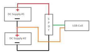
What you have is an SPDT - Single Pole Double Throw Momentary switch. When the handle is in the "up" position, the center and bottom contacts form a complete circuit. When the handle is in the "down" position, the center and top contacts form a complete circuit. When you release the handle, it returns to the center position and does not make contact with either the upper or lower contacts, forming an "open" circuit.
I tried the link after re-reading your post, and I, too, get an error 404.
Don't use the link I posted. Just use www.ross-crain.com . That gets you to his personal website. Not sure where you have to go from there to get to the instruction page. You might have to fish around a bit. I didn't take time to do it, as I am in indoor HO. Just trying to help.
One last question then - this diagram is to run the power from the ACC on the controller/power supply and that is great, but do I need the diodes if I run the Switch from a DC power supply separate from the track power controller?
If I do need these diode things - what size do I need? Are the like resistors with different sizes?
By the way, that is a great page/site for wiring too - will save me a whole lot of questions I think, and that has to be good news for you guys
Okay, have just picked myself up from the floor and shaked off the "oh crap - now what" feeling.
Just looked at a site to buy some of these diodes and hell - there were about 50 different types, sizes colors, names and who knows what else! The obvious question then - what size diode do I need? 1 amp, 3 amp, 6 amp, X volts or what? I thought resistors was confusing - this (to me) is a night mare
Tony,
what are you using A/C or D/C as that will decide if diode's are required. If D/C this is the simple way! As you already know it would need to be a center off momentary switch.
I'd suggest you contact Crain, and see what he recommends. He should be able to tell you, based on the ratings of the LGB switch motors. OTOH, if you are running DC as the primary power supply, you MAY be able to avoid using the diodes. But I would caution you to be sure, so you don't burn out the motor. (Have you ever considered switching (pun intended) to HO and twin coil switch machines?
Just looked at a site to buy some of these diodes and hell - there were about 50 different types, sizes colors, names and who knows what else! The obvious question then - what size diode do I need? 1 amp, 3 amp, 6 amp, X volts or what?
First, with diodes the voltage rating is generally the failure voltage. That is how much voltage can it block before it fails. Therefore, for model train stuff (in the 12-18V range) I always use diodes rated 50V or higher. I think most of the ones I use are actually rated at 400V (1N4004). I'm not certain because I buy them in bulk (by the thousands), and not purchased any in about 20 years now.
Amps is a different story. Unfortunately all my g-gauge turnouts are at the other house so I cannot measure the current on one and just tell you. I'm thinking that 1 amp would work, especially since this is not continuous service, and most of them (like the 1N4004) have a 30 amp surge rating.
The other cool thing about diodes is that they are so inexpensive ($0.04) one can experiment without worrying about hurting the pocket book. If a single 1 amp diode burns out, one can just replace it with two in parallel with each other for 2 amps.
One last question then - this diagram is to run the power from the ACC on the controller/power supply and that is great, but do I need the diodes if I run the Switch from a DC power supply separate from the track power controller?
No. No diodes needed for DC, but then the direction of the turnout is controlled by the polarity of the DC supply, not the momentary switch. For DC control one would need a normal reversing switch arrangement as gator do 65 noted above.
Now I am completely and totally confused. Are we talking about the Layout being DC or are we talking about the Power Supply being DC?
All I want to do is be able to change the points on my Switches remotely rather than having to walk up to them and change them manually - that's it.
Here is what I thought I could do ...
And these are the Momentary Switches I am going to use (ON -OFF - ON):
If that is wrong or wont work because my layout is DC then to hell with it, I'll change the points manually.
The other option is to buy the LGB Remote Switch thing for $78 + tax that plugs into the ACC terminals and straight to the switch itself, straight forward and easy BUT not worth $78 bloody dollars plus tax plus shipping.
And yeah, I am getting frustrated with this and don't understand why it so damn difficult.
The only thing that matters is what kind of power you are using for the switch machines. It has nothing to do with the DC power going to the track. Now I'm not sure if you connect the switch machines to the same terminals on your power supply as you are using for the track, it is possible that you could experience a momentary drop in track voltage as you actuate a switch machine. Depends on the power available from the power pack. On my HO scale layout, I use a separate AC power supply for my turnout machines. (Though I could just as well have used a separate DC power supply, such as the little wall plugs that came with various electronic devices such as 4-line telephones, etc.
If the LGB turnout uses a single coil switch machine which requires applying DC at one polarity to move the turnout to one position and DC at the reverse polarity to move the turnout to the other position then a SPDT switch as you have picture will NOT work UNLESS you use TWO DC power supplies.
See attached.
To use ONE DC power supply you need DPDT toggle switches so the toggle switch can apply the correct DC polarity to the turnout motor to move the turnout in the desired direction.
If the LGB turnout uses a single coil switch machine which requires applying DC at one polarity to move the turnout to one position and DC at the reverse polarity to move the turnout to the other position then a SPDT switch as you have picture will NOT work UNLESS you use TWO DC power supplies.
Nothing we have said has is specifically related to the track power... just power supplies in general.
So let us back up and take it from the top.
1. I get the impression that you want to power the turnouts from the same power supply (the MRC-9500) that is used to power the train. Is that correct?
2. That power supply has three outputs. Variable DC, Fixed DC, and Fixed AC correct?
Yeah, I wasn't going to even bring that option up least we confuse him further.
Nothing we have said has is specifically related to the track power... just power supplies in general.
So let us back up and take it from the top.
1. I get the impression that you want to power the turnouts from the same power supply (the MRC-9500) that is used to power the train. Is that correct?
2. That power supply has three outputs. Variable DC, Fixed DC, and Fixed AC correct?
2. As such, it only has 2 connecting points, one for track power and the other for accessories.
Terminals:
"Variable DC:
These terminals are for the attachment of your Throttle pack 9900 to the mainline of your layout. If the direction of your locomotive does not match the position of your direction LED’s, simply reverse the wires going to these terminals.
Accessories
DC: These terminals supply DC voltage for use with accessories.Be careful to observe polarity when hooking up accessories. The output of the accessories DC voltage will be determined by the position of the scale/gauge switch, located on the bottom of the cabinet."
Tony,
To use D/C with the TO's you would need to get the switch I mentioned and wire it as per the diagram, it is the exact same thing as the factory switch just $70.00 dollars less!


")