Granite Gorge and Northern - Ohio (cont'd)


GandG_North

Member
Hi everyone.
This started out in the "Introduce Yourself" forum.
Here's the latest version of my layout. I've switched from Peco code 83 track to Peco code 100. 100 seems to be less money and better availability. Did require some geometry change since turnouts aren't dimensionally identical.
It hasn't turned out as smooth as I hoped it would, I'll have some grades that are a little more than I'd like. I've got the four turnouts on the right hand all at the same elevation and laying flat, when the original layout had 3 turnouts that were on a grade and sloped, so there's some work I can do there, just not sure how to go about it. Probably can't be done in the digital world, will just have to adjust things as the track is put down.
I've gotta run, will post more later.
BigGRacing, is there a way I can send you the AnyRail file? You asked for that earlier, I thought I had attached it, but I must have missed the part where it told me we can't post that type of file.
 

Attachments

  • GGN Rev_1 2022-02-09.jpg
    GGN Rev_1 2022-02-09.jpg
    456.8 KB · Views: 228
A consideration. I don't know that the last turnout in the yard buys you anything, and might even be the opposite. As shown each of the tracks off that last one will probably hold only a single car each, or a capacity of 2 (boxes in yellow below). By removing the turnout the capacity of the remaining single track is going to be 3 or 4 depending on car length (add boxes in green). That is, unless you are planning on storing cars on top of the turnout, in which case there is a net gain of 1 (both yellow an green boxes). Is the cost of a turnout worth that increase?

OR if you could extend both those sidings further to the left by one car length, that would change the story.

Yard Track.jpg
 
Thanks, Iron! Yes, I didn't think it made much sense for two sidings that only had room for one car each, didn't seem practical. Your idea is good. Plus, it saves the cost of turnout, switch motor, etc.
I can't extend those sidings to the left. The yellow line represents a cut in the cookie-cutter top plywood top., so to the left of that line, things are sloping upwards into the mountains.
 
Hi. Need some help with identifying reversing section. If I'm going about this the right way, I think I need rail gaps at the connection of Turnouts X11 and X13, and at connection of Turnouts X14 and X15. Is that correct?
The zip file is my AnyRail layout.
And do my track blocks (sections) make sense?
For now, my wish is to get to the point where I can run one train on the orange loop, and another train simultaneously on the yellow loop. Which I've been able to do on TrainPlayer. Then I'll go from there as I learn, and time and budget allow. It's going to be fishing time soon!
 

Attachments

  • GGN_1 Master_Rev1.zip
    76.1 KB · Views: 100
  • 2022.02.17 GGN Reversing Sections.jpg
    2022.02.17 GGN Reversing Sections.jpg
    547.8 KB · Views: 112
Need some help with identifying reversing section. If I'm going about this the right way, I think I need rail gaps at the connection of Turnouts X11 and X13, and at connection of Turnouts X14 and X15. Is that correct?

And do my track blocks (sections) make sense?
For now, my wish is to get to the point where I can run one train on the orange loop, and another train simultaneously on the yellow loop.
Well all looks good to me for what you want to do at the most simple level. That assumes just one train per loop with its own power, and one in the yard. The issue is with the reversing sections as they reverse between the two loops. The power reversing switch instead of just reversing polarity will also have to switch between the two loops' power supplies. Run the train into one of the reversing loops. Stop. Switch to other powers supply. Make certain other power supply is right direction. Proceed.

What this doesn't allow you to do is easily run a train from one loop to the other via the X11-13 and X14-15 crossovers. Crossing those gaps will change the train from one power supply to the other creating possible double voltage or double short circuits as they do.

To really do this as a fully functional multiple train DC layout will require several more blocks and consequently block controllers on every single block. This is why DCC is so much simpler.
 
Last edited:
To really do this as a fully functional multiple train DC layout will require several more blocks and consequently block controllers on every single block. This is why DCC is so much simpler.
Thanks, Iron. Agree with your DCC assessment. I don't want to become a constant DPDT switch thrower. Just the cost of DCC is keeping me away from it for now. I'd be happy to just have two trains on DC to start, which looks like it will be inexpensive and simple. I'll be at the opposite end of what Jerry Hessler (did with his fully automated PC controlled GGN layout...on youtube if you haven't seen his videos), but that would be a fun way to spend some $$$.
 
Maybe I need to rethink this DC stuff. The cost of two decent power packs for DC (something like an MRC 1370) is going to run around $100.
But it looks like I could get a starter pack from NCE (PowerCab 524025) for around $200, which is much less than what I thought the entry price for DCC was going to cost.
I realize that the DCC locomotive(s) is going to cost a little more, too.
DCC would also have the advantage of being easier to add auto reversing in the future.
thinking....thinking....
 
Made some progress, which is going to be more difficult in the coming months with the weather warming up, because I hear some fish calling my name.
That's my first DCC loco sitting there, was able to run it on a small section of track just to play around with it. And was also able to figure out how to turn down the volume. Jeesh!
I must have gotten creative with the "yard" where the orange boxcar is sitting, as it doesn't match the published layout. I can't run a complete loop yet because there are some missing sections of track. Well, that and a whole lot of wiring that needs done.
I still intend to someday tear up all this track and replace it, hopefully with code 83 Peco tracks and turnouts. With the way things are looking in the world right now, it's hard to spend that kind of money at the moment. So I'm looking at getting some flex track to fill in the missing spots, maybe enough to also eliminate some of the sections of Atlas brass track that's used on the bridges and short pieces of sectional track from 40 years ago. And once that's done, I guess I'll be getting some practice doing the wiring/soldering/etc.
That box of Atlas bridge piers has a price tag of $1.25 from 40 years ago. I guess $5.50-$6.00 current pricing isn't so bad. This is not an inexpensive hobby, very unfortunately.
I wish the best for any of you with friends and family in Ukraine, and I hope for the worst for the schmuck in Russia.
Peace.
IMG_20220306_180800413.jpg
 
Thanks, Gary!
It is 2-19/32, precisely. The support piers are two Atlas #81 piers that have one end cut off, then glued together. There is just a very slight gap between the Warren Truss bridges. The center distance is based on the two 45 degree crossings that have a 1" track section between them.
I attached that temporary cardboard guardrail around the layout after I was playing around with an old Life Like DC loco and power pack that I had from years ago, accidently ran it off the end of a track, and it fell to the basement floor and broke :(. I think it's repairable. I don't want that to happen to that new DCC loco, no sir!
 
Hello everyone. Just some updates on the layout.
After a lot of research and looking around and researching some more, I decided to go with MegaPoints Controllers out of the UK for my turnout controls. I purchased an Arduino Mega and an Arduino Motor Shield that I intended to use for this purpose, but got cold feet and decided for now I don't want to dive into Arduino code, I want something more plug-n-play, hence the MegaPoints. I plan on using Arduino in the future for other purposes.
I did purchase the DCC interface from MegaPoints, but other than installing it into the "control panel", I haven't done anything with it yet.
Here are some photos of the "control panel" I made, using the MegaPoints boards. I don't have much room around the layout, and I want to keep the control panel as small as possible, so I just used the box that the MegaPoints items were shipped in to build this mock-up to give me an idea of how small I can go. This first go-around is a little too small, I need to go 10-20% bigger so I have enough room for the indicator LEDs. But this confirms that I can go small enough that the panel can fit on my layout. I just have to come up with a design and then build it. I've thought about maybe incorporating it into the roof of a building. But not sure if that's a little too goofy or not. Still pondering.
IMG_0937.JPG


Control Panel 3.JPG


Control Panel 2.JPG


I purchased the Frog Relay/Driver Board and the Relay board from MegaPoints. I have old Atlas Custom Line turnouts on my layout, and they act inconsistently. There are two #6 turnouts, and they cause problems with the DCC because the frog is plastic. I get stalled locomotives when I'm going slow and pauses when I'm running the locos a little faster. Faster still, then no problems. I have a solution that I found on the YouTubes in mind for that problem that I am going to attempt. The other turnouts are all #4s, which have pot metal frogs which can't be soldered, but again YouTubes offer a solution for that which I am going to try. I'm not convinced though that there isn't some other issue with all the turnouts because I'll get indications of a short at times (the power light on the NEC DCC panel will turn off and on as a loco passes over the turnout), so I have to dig a little deeper on the turnout issues. But normally I can run without interruption, I'd just like to get these to behave all the time.

Here's a turnout servo using the MegaPoints servo mount. The mounts are very inexpensive, around $2.50 - $3.00 each with shipping. They are laser cut in wood ply material (not solid wood), and are advertised as if you can just pop them out of the "sheet" they are printed on, but in reality most of them needed some extra cutting along the laser cut lines, or else they would break. The holes for mounting them to the underside of the layout (plywood, in my case) are too small and must be enlarged or else the material will break and peel away around the holes. Once the shapes are punched out of their sheet, you glue the pieces together with superglue. All in all, they work fine and I would use them again. I see in this picture one of my mounting screws isn't quite set all the way. Oops. Working under a layout at my age is a PITA. I still have 5 more servos to place.
Servo Mount 1.JPG

Here's a shot at my unfinished mountain attempt. Here I'm just trying to get a picture in my mind of what the scenery is going to look like and get some idea of where to go with this. The scenery part of it has been a logjam in my mind, so just trying to kick some ideas around. This is a very crude mock-up. I'm hoping to come up with a way to place the mountains such that they can be lifted off if the layout ever has to be moved, without it looking like it is a mountain that can be lifted off.
Mountain 1.JPG


Here's a practice attempt at a bridge abutment out of Lowe's green foam panel:
Bridge Abutment 1.JPG


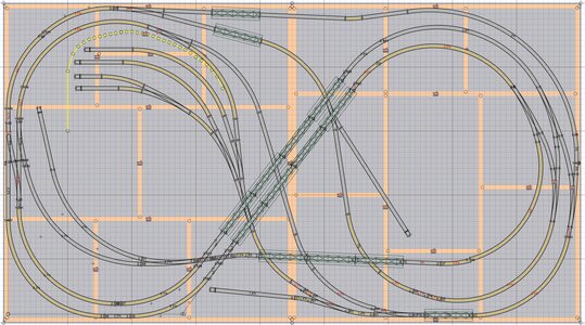
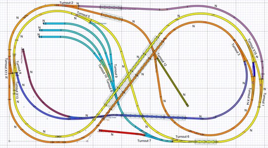
And lastly, here's a somewhat overall view of the layout:
Overall 1.JPG


That's all for now. I'll post some further updates as I go along. At the moment, fishing is interfering with my railroad hobby. Or maybe it is the other way around.
 
Here's an update on my first attempt at one of four tunnels. This is, hopefully, the most difficult of the four, since it is curved (well, all of them will be) and has a slight elevation difference between the two tracks. It was a lot of work (close to 12 hours!!), but as it went along, found ways to make the next one easier. I know there are easier ways to make tunnels, but I had started down this path and stuck with it. It gave me a chance to practice carving rock faces into plaster, knowing that most of this work in the back of the tunnel isn't going to be seen by anyone. I tried several methods here just to get an idea how they look. While they look not so good when the tunnel is on the bench, when it is set in place, it looks better than I thought it would. I'm going to try and use aluminum foil molds on the next tunnels. I haven't painted rocks before, so going to do some practice before painting this tunnel.
I also "kit bashed" the tunnel portals. I bought these back in the early 80's (they are still available!). The track centers are too far apart for a standard double wide portal, and too close together for two single portals, so I did some cutting and gluing and will patch up and paint, and in the end, hope they look like one single portal. I may cut and chisel the two central depressions, so it looks like a single wider one. Unfortunately, probably due to age, the top of one of the portals has an arch it in, which I hope to disguise with scenery.
I'll also make the rough openings in the tunnel itself larger. I couldn't make the plaster coat very thick. If it was thicker, I could make the cuts in the walls deeper and more defined. As it was, for this one the outer tunnel had to have a wall shaved back at the exit to clear tanker cars as they came through.
I've got some ballast on order from Arizona Rock and Mineral, the project manager slipped up and didn't get the purchase order placed early enough.
Coming through!


IMG_20220603_090143.jpg

IMG_20220603_090134.jpg


IMG_20220603_120942.jpg

IMG_20220603_121152.jpg
 
When Atlas came out with an 18" bridge many years ago, it seemed to me, like the way to go, as it could eliminate a bridge pier underneath, where I might want to put some scenery instead. I wasn't crazy about the 9" Warren Truss Bridge, as they called it, as it seemed shorter than many prototypes I'd seen. Also, with an 18" bridge, maybe 'd use 1/2 a section of flex track on it, instead of 9" sections of rail.
 
When Atlas came out with an 18" bridge many years ago, it seemed to me, like the way to go, as it could eliminate a bridge pier underneath, where I might want to put some scenery instead. I wasn't crazy about the 9" Warren Truss Bridge, as they called it, as it seemed shorter than many prototypes I'd seen. Also, with an 18" bridge, maybe 'd use 1/2 a section of flex track on it, instead of 9" sections of rail.
I'll check that out. The bridges are one of the things on my wish list to upgrade.
 
Nice job on matching up the tunnel portals. I've used these several times in the past, and know that the material can be tricky to cut.

I've looked at this layout, + the Central Midland, Berkshire Valley Lines (4x10 or 12) and the corner industrial layout, with the wye, in terms of either modifying them, or combining them, into a larger 'system,' if I had the space. Now that Atlas also makes 24" radius curves, in addition to 18 and 22" curved sections, if I were to build these I might go with 22 & 24" curves, instead of 18 and 22" curves in some places. It would mean I might need to add some plywood in the middle of the table, so the 24" curves don't hang off the sides of the table. I don't see that as a major problem.

In terms of the GG&N, putting a mountain on the left side of the plan, and some sort of town on the right, to 'change things up,' and make the layout less recognizeable to the the trained eyes, might add some an avenue to being out some creativity, which typically you don't see when people build the plan.

If I were to ever build one of the Woodland Scenic layouts, with the styrafoam, I might do something similar, to make it more of an original design.


Back
Top