Gateway Subdivision


Thank you Jeff!
I contemplated a "helix"
It was certainly daunting for me. I hadn't done one before. And this one is two separate helices', going in opposite directions. Once I knew a few key points, the rest fell into place.
Kudos to your lofty goals.
Right!? Micro layouts! Toma sections! Shelf layouts! I don't want small! I went a very long time with out. I envy the 20-25-30-35 year model railroader. Tho, I do understand the wanting to down size. But that is just not me! o_O
have the skill
I got lucky. My dad had always worked with wood, so I grew up with a garage full of wood working equipment.
 
Thank you Dave!
Are you modeling the Malin station, or some of those scenes on your layout?
Not the station but the packing sheds on the right end of the red brick shed. They were wood with docks to load refer cars. They are gone now, burnt/torn down. I had pictures of them, but they were on the camera that got stolen last year.
There was a feed lot & rail loading pens even further right of the packing sheds. I'm going to model the loading pens.
My grain elevator will be wood, but I'm going to use the name.
And since you and Rick mentioned the history, stay tuned, I've got some more coming up. ;)
 
I've been pushing thru the bench work, it makes such a mess, I just want to get it done.
The upper-level logging bench work is done, thus completing all the major bench work. All bare wood gets painted top & bottom before the final install. Now I'll make splice plated for all the joints, install facia brackets on the main level peninsula, and add some channel iron to a section of bench work.
IMG_0138.JPG


Over at the window, the bench work has to span a distance of about five feet. When I had the room built, I had a smaller window put in, as a result there is no support for the backets were I need them under the window.
IMG_0130.JPG

Besides the stiffeners I added for the facia and back of the shelf, I added a couple pieces of channel.
1" wide, with 3/8" legs, I used #10x24 11/4"pan head machine screws to attach them.
IMG_0132.JPG

Installed.
IMG_0129.JPG


You can see also in the above pic that I've started to put the "L" brackets on the peninsula for the Masonite facia. From the plans, it looks like I might have to install a small piece of board for switch control mounting, about were the hammer is, but the rest of the peninsula will be masonite, held by the brackets. I did add three stiffeners under the end of the peninsula since I didn't go around the outside edge.
I'm contemplating using the dry wall shims for going around the end of the staging peninsula.
Onward!
 
In the continuing effort to restrict warpage/movement of the wood in the layout, it all gets painted. You've seen the staging level painted, now it's time for the main level & the logging level benchwork to get paint. The bottom side of the main level & logging level will get painted white. I had a gallon of interior white that came with the house, so I got a freebie there.
I managed to get about two thirds of the under sides painted until I ran out of room. When they're dry I'll put them back on their brackets and use them to hold the unpainted pieces.
IMG_0178.JPG


Being as I wanted to paint the bench work, including the top side, I had a concern whether I could effectively glue the foam to a painted surface.
Having one side completely sealed and the other side open on piece of wood is not good if you're trying to control movement. So it's a quick experiment, paint a piece of plywood, let it dry for 4-5 days, glue a piece of foam to it.
IMG_20220329_075822701.jpg

IMG_20220407_153033190.jpg

Well that was a success. I could not pry the foam off of there for nothing. I used the foam safe liquid nails, with 3 "X's" the length of the paint section.
 
Here is some more of the Malin history I had mentioned earlier, my favorite to collect, paper work! This paper work came out of a potato packing warehouse. It was located at the right of the red cinder block warehouse shown above. . I had pictures of it saved on a sd disc, but it was in the in the case when the camera got stolen. It has since been torn down.
The potato's came in on the lower level, were they were processed and moved up to the upper level, were they were packed, & put on rail cars. There were four of these sheds in a row, all big enough that they all had three separate doors on the track to load cars from. At one end of the main level was an enclosed office. It appeared that when they took the file cabinets, the contents were dumped on the floor and left. There was a pile of paper in the office, and on the far side of the main level, all covered in pigeon---stuff! There was enough of the paper work to sort through and come up with some nice clean pieces. Quite a few with dates.
Note Pads.......
IMG_0162.JPG


IMG_0164.JPG

I have the pages in those walmart poster display boards, I had a hard time getting a picture with out high glare or reflections in it.
 
Good day Everybody! While I was working on the main level this summer, I kept the staging bench work out in the shop while the temps are mild, but we're starting to get bigger temp swings now, so I moved it all in the layout room, just setting on the brackets loose, so I can move it around while working on the main level.

Installing foam on the main level......
IMG_0217.JPG

IMG_0228.JPG

IMG_0227.JPG


With the foam on the main level, it's time to install the peninsula divide. I used 3/16 press board (that's what I've always called it)
I used Evergreen styrene "H" beam as a joint between the press board pieces.
IMG_0246.JPG

IMG_0242.JPG

IMG_0243.JPG


I painted the divide the same blue paint used through out. That's the logging bench work on the staging brackets above, After I got the peninsula painted, the logging bench work went up on it's brackets.
With the foam down, I can layout the track center lines., and lay some cork down.
IMG_0322.JPG

On one of the trips into the layout room, I figured it might happen, and it did, I bumped the end of the peninsula with my hip. Oh boy, can't do that too many times! The next trip to town I got a concrete anchor, that's better...... (left leg)
IMG_0220.JPG

Everybody have a great day!
 

Attachments

  • IMG_0322.JPG
    IMG_0322.JPG
    82.9 KB · Views: 52
As seen in the above pictures, after painting the peninsula divide, I installed the logging RR bench work. Like the main level, I installed splice plates at the joints. Installing these helped assure evenness between panels and stiffen the bench work.
All of the splice plates are 4 inches wide, 2 inches each side of the joint, and deep enough to span the distance between the end of the shelf bracket and the facia board. You can just make out the pencil outline of the splice plate on the bench work by the screws. That let me see were to place the screws.
IMG_0323.JPG


I lined up the splice plate underneath the joint, siting thru the joint to line up the center mark on the plate, apply a little clamping force, drive home the screws.
IMG_0324.JPG

IMG_0325.JPG


I have LED tube lites coming for mounting under the logging bench work. In the mean time, I'll cut the foam for the logging bench work and get that mess out of the way.
 
Thank you Tom. This build has been a challenge! The first layout's challenge was, that was the first layout! The challenge on this one was, the helix build, and, an all metal lift up for the walkthru door.
Yes, this helix is a crawl under, it is 52 plus inches across the inside opening, so there is a fair amount of room inside, but the crawling under is a pia. I was thinking of finding something like a low slung mechanics creeper to help with the sliding under the thing.....
 
Meanwhile, over at the entrance door, a lift up build has been going on. On layout I, I had a simple plywood "T" shape with a couple of plate girder bridges on it. Each end sat on wood blocks that were adjustable, for track alignment.
IMG_2545.JPG


Worked pretty good, except, during weather swings. With everything being wood, on the expansion cycle, I would have to sand the end of the T for the bridge to fit. Then, on a contraction cycle, the gap would be pretty big, I was amazed at how big a gap trains would negotiate.......
Anyway, on this layout, I wanted to try and eliminate all the expansion/contraction that I could, so I figured something all metal.
With weight a consideration, I would build as much of the lift up that I could out of aluminum.
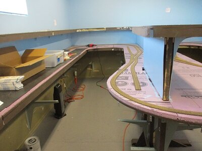
I fashioned alum. ends for the benchwork I found these slides that extend 36 inches, for a total overall rise of over six feet.
IMG_20220830_132218407.jpg

IMG_20220830_132241362.jpg

The slides, being steel, are pretty heavy, and I didn't want their weight hanging on the benchwork, so I installed adjustment feet at the bottom.
I installed 1x1 alum. angle around the perimeter of the alum. panels for rigidity.
IMG_20221004_150127823.jpg


I did the same for the top piece, 1x1 down the sides and a piece of 3/4 X 3/4 steel angle iron down the center to help get the bow out of it.
IMG_20220830_132300286.jpg


1 x 1 angle across the end of the top piece bolt it to the panels on the slides.
IMG_20220830_132450909.jpg


Looking at a cross section view of HO code 83 rail, that's pretty small, so I figured doing oversized mounting holes for the slides to benchwork, panels to slides, and top piece to slide panels would give me enough adjustment.
I need foam on the top piece to bring the track up to grade, but gluing it on alum. was a concern. I experimented with a scrap piece of alum., taking a piece of 120 grit sandpaper to scuff up the surface, then cleaned it with alcohol. Foam safe adhesive, some weight and two days later, I tried to pull the foam off the alum. It took a little bit of effort to break it loose, but did make me wonder if I was going to have problems later on. I do have several pieces of plywood left over from the benchwork, so I bolted one to the top piece to glue the foam to.
Wonder if the adhesive needs the help of porosity to function?
IMG_20221004_150632700.jpg


The 1x4 underneath gives my hand something to lift on. There is a catch on each side, made from 1x1 angle, (by the door handle.)
IMG_20221004_150519275.jpg
 
Thru the build of this thing, I was thinking I could find an assistant in getting this thing lifted up, like a gas strut. The top weighs 15.5 pounds, the second stage extension of the slides have some resistance to them, maybe 2 or 3 pounds apiece, for a total of 20-21 pounds. Struts with that low a rating are short 10-12 inches long. I found a strut that at full extension is 36 inches long, and has a port in the end so you can adjust the pressure.
The problem is, that the rod only extends 15 inches, which means, the lift up will only raise 15 inches.
Lifting 20 lbs is not all that bad, but, that part where I have to lift it up over my head, and hold it to engage the stops, that's where I was wanting some help. Admittedly, I am poor on strut physics..... anybody do struts out there?.......
Might have to punt on this one.......
I have seen it mentioned more than once on a variety of forums....KISS!
 
I never did care for point rails relying on contact with the stock rail for power, so on the previous layout I soldered the point rails to the stock rails on the bottom. The pink(ish) color is nail polish I painted on the jumpers when I was doing the initial positioning, to mark the roadbed so I knew were to dig grooves for the wires to fit.
IMG_20221101_024629983.jpg


That's kind of a pia, so on the new switches for the layout, I'm soldering the jumpers on the top side.
I'm using a fiberglass scratch brush to clean the rail, liquid flux, Kester solder and a Hakko variable temp soldering iron.
IMG_20221101_035432971.jpg

Jumper wires cut & bent to shape, small pieces of solder.
IMG_20221030_003850588.jpg


clean the rail.... at arrows, doesn't show very well...
IMG_20221030_003137096_HDR.jpg


A --touch-- of flux to the clean areas, set the jumper in place, along with a piece of solder, arrow......
IMG_20221030_004051653.jpg


The soldering tip set at 450 degrees, a quick jab into the tip cleaner, then melt a small drop of solder on the bottom of the tip, (to convey heat,) touch it to the blob of solder and drag back to spread the solder out. Repeat for other end. The liquid flux helps pull the solder up the wire when heat is applied.
IMG_20221031_122308436.jpg


A test that there is no binding......good to go.....
IMG_20221031_123114133.jpg
 
Something I had been wanting to do for a while now was make a new test track. The first one I had put together with a piece of plywood, that some of the "ply" was buckled up on it, and I laid some really old Atlas brass track on top of that. I made it work for what it was.
With the bench work done, the foam cut to size, I had some materials left over, so I thought I would take them back & buy a piece of plywood for a new test board. That worked out pretty good, I returned 2- 1"x4"x8ft pine boards, 1-2"x4"x8ft, 3- 4x8 sheets of 1 inch rigid foam.
After getting the piece of plywood I wanted, lunch, and buying the Atlas NS track W/roadbed, I still had $40.00 cash for my pocket!
The new test track, I just finished soldering all the joints on it. 24" radius
IMG_20221029_143844175.jpg

IMG_20221029_143901824.jpg


Back
Top