ModelRailroadForums.com is a free Model Railroad Discussion Forum and photo gallery. We cover all scales and sizes of model railroads. Online since 2002, it's one of the oldest and largest model railroad forums on the web. Whether you're a master model railroader or just getting started, you'll find something of interest here.
Does anybody still make a constant light module for a non-DCC engine? Like the Walthers 961, from eons ago. I'm still DC and building engines. I have a 962 (2-amp) but it is too big. Yes, I found one on EBAY, but are these still made? It can be either reversing or non, I don't care at this point. And no, I can't use LEDs. I'm using the Cal-Scale GE 44-ton headlights, which are tiny, and the biggest thing I can fit into them are 1.2mm micro bulbs, which I have a ton of. I could build a diode array, but I'd rather find a single module/chip that's fairly small and reliable. How about a 4-pin chip regulator that the 961 is based on? Open for suggestions.
When I was still running in DC, I was using the Utah Pacific CLU-96. It is a constant lighting unit that gives you reversing headlights, backup lights and constant lighting for either cab lights, number boards, etc.
It comes as a small printed circuit board with diodes (assembly required).
You should be able to find just about anywhere. Utah Pacific products is currently owned by Tomar Industries and is also available thru Walthers.
I also see they have a LU-66, which is what I need, but I think I'll try a 4-pin bridge rectifier with the output pins soldered together. Since the input is DC, that just acts as a diode array. You can't beat it for around $.50 and they're very small. Not reversing, but on a switcher I don't really care. I miss Radio Shack. For my FP-7s I think I might try your suggestion, though, for all the added options.
It's been a while, but IIRC I used to make a "six pack" of diodes, and different connections on the ends give different effects. The one I used was normal brightness in the forward direction, dim to the rear. I never thought a PCB would make things any easier, certainly making it a little bigger. I recall it was pretty easy to assemble.
Both the 6 diode circuits shown there can be implemented in a six pack physical configuration without any jumper wires. I suggest 1N4007's for HO. by that I mean like:
123
456
looking at one end
It's tempting to think about using a regulator, but after all is said and done, there are too many complications. A linear regulator will dissipate much more heat than the bulb itself, and needs capacitors to remain stable. Some also can't function on low throttle settings, where a diode circuit will. An LDO regulator doesn't have this problem but it has the other ones. You have to rectify the source first, that's a diode bridge and substantially large capacitor to begin with.
I would like to put constant directional lighting (like the Ron Paisley one above for Double Light Dimming in both directions) into A Bowser 2-8-2 which also has a tender backup light. The problem is the motor is grounded to the frame and the tender is providing a direct pickup to the other side of the motor. The 1.5 v bulbs are already installed. So in this circuit would the diode/light portion be cut in between the tender pickup and connection to the motor?
Hi,
I resolved the running issues after disconnecting all the previous wiring. Right now the engine is running fine with both of the lights disconnected, and just one wire running from the left side of the motor to the tender. I have plenty of flat bridge rectifiers, diodes, and resistors.
I was hoping to get some clues about the lights from the existing (i.e. previous to your mods) configuration. If it had 1.5V bulbs, it must also have had diodes. If there were no diodes, then they aren't 1.5V lamps and you have an additional need, to change them. Anyway, since one bulb is in the engine and the other in the tender, you can keep only one wire between engine and tender by putting 3 of the diodes in each one. I want to show you a drawing but I don't have time until tonight.
Thanks guys. I appreciate your time. They had some type of lighting unit made years ago encased in a black blob (I'm sure there were diodes in there) made by Idea's Unlimited. There was a short somewhere in the engine so I threw them out.
This will allow you to use only one wire between engine and tender:
View attachment 125494
For all-wheel pickup, you need two more wires: View attachment 125496
[/QUOTE ]Diesel, perfect drawing I could understand. I tested it with the 6 diodes and single wire connection, and it worked perfectly. Exactly what I was looking for. Thanks.
Diesel,
I hooked up the circuit. The lights work but they are working opposite of the engine direction. I checked all the diodes and they are fine and I double checked their polarity with your drawing. Should I just swap the boards in the engine and tender?
Diesel,
I hooked up the circuit. The lights work but they are working opposite of the engine direction. I checked all the diodes and they are fine and I double checked their polarity with your drawing. Should I just swap the boards in the engine and tender?
Does the engine run in the same direction as your other engines, or does it run the opposite? Place one of your other engines on your track, and run it right to left in front of you. Stop that engine, and remove it from the track. Place your opposite-lit engine on the track, and without flipping the direction switch, open the throttle. Does it run right to left, like the previous engine? If not, you have the motor wired backwards.
If I remember right, + on the R rail and - on the left will cause a forward motion. I forgot about that, but I think I "lucked out" and did it right in the second diagram. Anyway, check and confirm the motor polarity first and then swap boards if the lights are wrong.
I checked it with 2 other engines and they all ran in the same direction. So the motor is wired backwards.
When the engine runs forwards, the engine light is dim and the backup light bright. Just the opposite in reverse.
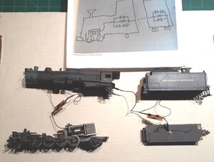
Just so I didn't mess up, I took some photos. They are in reverse order.
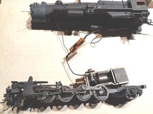
The motor is grounded to the frame with right rail pickup
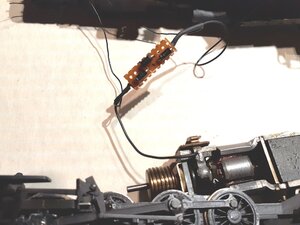
The wire from motor is connected to the diode board. One wire going to engine light from each side of board.
Wire from rear of board going to tender
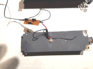
On tender, wire from engine coming in on left with wires to backup light coming from each side of diode board.
Wire from rear of tender board going to left rail tender pickups
So I should just unsoldered each board and swap them?


")