Csi: Ttfh


paper-tiger

Member
Crime Scene Investigation: Train Table From Heaven

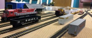
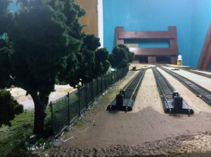
Hello, all! I'm a newcomer to the forum and to the hobby, but I have very swiftly learned that you are a friendly community interested in a challenge and willing to help. The following is from a train table that I snatched up from the local non-prof secondhand store. I saw it and was absolutely flabbergasted by the resale price. (The extended story is on the blog entry at http://www.paper-tiger.org/2014/11/08/train-table-from-heaven/) I recognized that it was an incredible HO scale layout that was uncannily similar but ultimately superior to what I was attempting at the time, but I didn't really know what it was. I still don't understand and can't really make it run until I do. If anyone could help me understand what is going on with this, I would love it. I know third-hand that the man who donated it built it in 6th grade and had no children or grandchildren interested in it, so he gave it away. I have attempted to find him through the non-prof that sold it, local classifieds, and the local websites with no luck so far.
I talked to a local (ie: 2 hour drive one-way) hobby shop dealer about it and bought an older DC controller module which allowed me to connect it in a way that got certain parts of the layout working if I had the right combination of switches, but... I'm lost. I would seriously appreciate some help. FB, my blog and local contacts have netted me zero leads. Other than that mystery figure who donated this amazing base layout, I am the only model railroader I know of in the region, and I'm a total newbie. I'll take pictures of anything you want. Your help would be desperately appreciated!!!
And my further apologies, my photos are too hi-res for the forum to accept remotely, it seems, so I must link.

http://www.paper-tiger.org/2014/11/08/train-table-from-heaven/

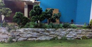
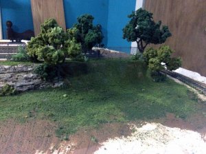
It's so beautiful... The hills between tracks are too extreme to create a scenic countryside layout from, but it might be a really nice "urban" scene with the right artistry... I just... I saw that it was a gem, but I don't know its real potential. Help me, Sherlock Holmes, please?
(If you want a pic or video of something you don't see here, tell me about it and I will (try to) make it happen. In video or stills as required... I currently have it connected to a vintage DC controller that works 3/4 of the way around as long as I have everything set to 'Cab A'... Pretty sure that's just luck. Finding the creator would be a gold mine!)

I have no idea what's going on here, and I would love to. You know just by looking at it. Please help!
 
From the pictures, it looks to be set up in 'blocks', with two controls, cab a and cab b, so that you could run two different engines. The switches on the side are used to determine which cab is powering the different parts of the track.

The blocks are electrically insulated from each other, either by small gaps in the rail, or by using insulated plastic rail joiners, which are typically yellow or orange.

The fact that you can go most of the way around suggests there might be a broken wire somewhere.

If it were me, I would examine the track really closely to find out where the different blocks start and stop, and use a marker to note that on the plywood. (Check near the turnouts). Then I would trace the wiring to cross reference the switches for each block, and then use a multimeter to to find any wiring issues.

Finding a local person to give you a hand is probably a great idea, but you'd have to get on I95 and head north for a couple of days until it ended to find me, so I can't help.


Sent from my Vic20 using Java Moose
 
It looks fairly straight forward. As stated in flc2117's post above It is wired for 2 train control. Looking at the controls picture I can only guess that the green boxes with red buttons are for operating some accessory like a log unloader. The black switches are standard Atlas controls. The first unit with two red horizontal switches is a reversing-loop controller. Since I don't see any reversing loops in the track plan, I am guessing it is wired to the turn table. Following the blue&yellow wires that come out of its top should confirm that, or lead you to the reversing section.

The next set of twelve vertical green switches are selector switches that just choose between cabA or B. As you already figured out, switching them all to cab-A should let that cab control the whole layout. Since it does not there is probably a broken or loose wire.
Here is what I would recommend.
1. connect your power to cab a (sounds like you have already done this)
2. Draw a diagram of the layout.
3. put a loco on the track in a place you know is working.
4. flip all the selectors to cab B.
5. turn the power on
6. flip exactly 1 selector and only 1 selector to cab a. If the loco moves you have found the switch for that section of track. When you find this, run the loco as far forward and back as possible before it stops on either end. Mark on your track diagram that place and that much distance. Label that selector switch to match that part of the layout diagram. flip that section back to cab b.
7. move the loco to the next section of track and repeat.

This will give you a map of the working sections of the layout.

For the unworking sections you will either have to find the wire coming from that section and track and trace backwards, or go from the switches that didn't map anywhere and trace forward. But this should be easier since it has to be one of the ones not mapped. Failing that, it could be that the common wire or the common rail has failed to those sections of track. This will be a bit harder to track down, but lets worry about that after you map as much as possible.

A VERY common problem with these control switches is that people will screw the wires on so tightly it breaks the wire. So even though a wire looks connected it could be broken just under the edge of the connection screw.

Finally the little switches to the far right are for turnout control. The power input from the switches side (those two blue wires hanging down) would be the "AC OUT" of your power supply. To activate you move the blue switch to one side or the other and press in. You should be able to "map" them by listening for the buzz. Do NOT hold them down just press and let go. Holding them down will melt down the switch motors.

BTW - This is a "twice around at elevation" layout. It has two sidings for two simultaneous train operation. One of my favorite schemes. Looks like the track is well laid. Personally, I would not even consider "converting to DCC" until you have gotten all this working and and used it enough to understand it. Then converting to DCC will be much easier and you will appreciate it much more.

P.S. Finally this is more easy stuff. If it doesn't sound easy it is because I've not stated something clearly. Just ask again and I or others will try to clarify.
 
Last edited by a moderator:
Aha! I knew you guys would know just what to do. I've got my work cut out for me, for the next few days (weeks). I'll update once I figure out what's what.
​Thank you!!!
 
Just wanted to let y'all know that I have managed to get this silly thing figured out enough to use the main line and some of the switching yard! It is still buggy, but I'm working slowly but steadily away at figuring it out. Definitely gives me an appreciation for how 'easy' my EZ-Track layout really is. Thank you all for your suggestions in getting us started. :D
IMG_1792.jpg
Still no idea what those green buttons are for, and I have six switch buttons (five of which are connected) and I've associated each of those with a switch somewhere on the layout, but there are about 7 more that don't appear to connect to anything.
Ongoing project, for sure!
 
That is an amazing find and all for only $10! Whether it worked or not was worth the price for what you have. Good to know that you have at least apart of it running.
 
Still no idea what those green buttons are for, and I have six switch buttons (five of which are connected) and I've associated each of those with a switch somewhere on the layout, but there are
The big green boxes with red buttons that say Tyco on them? Those would have been for some sort of accessory like a whistling crossing gate, log un-loader, etc. The only thing I see from the pictures that might be one of these items would be that big grey thing in the middle of the layout on that side track. I'm guessing that the items may have been removed.
 
As an update: The green buttons were apparently for turning "on" cabs 1 and 2. They were simply connected to the cab a and cab b off the reverser switches. In running the layout I have started to understand the blocks, but I have also converted to "extreme starter" DCC with the Bachmann EZ Command on this 4x8. It is still wired in blocks for DC and works beautifully except for a specific place where it doesn't trigger a 'short', but stops responding until you push it far enough forward. I've cleaned EVERYTHING until it literally shines, re-soldered specific places, and still encounter these shorts in operation - not electrical shorts, because I can usually push them along until they continue alone. Either that, or the sound stops and I can push them along until it start again and I can restart by the controller. I'm to the point where I seem to need to re-wire the whole damn thing. I've read the wiring for dcc pages and watched quite a lot of "basic model train wiring" videos that already go above my head. If someone can link me to a place that SHOWS what the actual hell you need to connect a "bus wire" to your dcc controller, that would be a really helpful place to start. Knowing someone who does this somewhat locally would be the prizewinner. :(
 
I've read the wiring for dcc pages and watched quite a lot of "basic model train wiring" videos that already go above my head. If someone can link me to a place that SHOWS what the actual hell you need to connect a "bus wire" to your dcc controller, that would be a really helpful place to start.
I have to say that I am baffled.

To rewire for DCC, the first thing I would say is that for a 4x8 layout you don't really need a power bus. I did that once and then realized how much of a waste of time, money, and effort that was. Also since the layout is already broken into DC blocks that aren't working it means the feeders aren't working right to begin with. Just replacing them with a bus will result in the same problems. So if you are certain you want to do this, the first thing I would do is to go through and replace all the insulated joiners with metal ones. I'm sorry I'm not more help. If I wasn't about 900 miles away I would swing by and take a look.
 
You don`t need a bus for this layout, it would be an unnecessary complication.
For the dead section of track, simply go to your local hardware store, and buy an inexpensive test light. Obviously, you know part of the track is not getting power. So, again, the easiest thing to do is place a locomotive on the rails in the dead spot, clip the test lead from the test light to one rail, and touch THE SAME RAIL on the section just ahead or behind the engine. If the light works, you have either a bad wire or rail joiner between those sections. Since the spot is dead, there will also be a bad or non conducting joiner behind the engine. If you can't find anything on that rail, move the clip to the other rail, and test that side.
 
Thank you VERY MUCH everybody (and especially IronHorseman) for your patience as I try to figure this thing out! Some soldering joiners here and there and a couple of feeder wires to the problem area seems to have solved the dead spots, for the time being. It highlighted some other issues, of course (doesn't it always) but I have a better idea of what to do about it, now!
 
If you really want to convert it to DCC this book might help. http://www.amazon.com/dp/0890247935...TF8&colid=1JCDDDFHO2L9H&coliid=I3GDCA79V5JLRH

If you want to repair and figure out what you have this book will help http://www.amazon.com/Horizon-Hobby...catcorr&keywords=atlas+guide+to+layout+wiring

Both books are available through the forum bookstores as well (usually cheaper), but I could not get the links to work just now, you could try later.

DC wiring is much more complex then DCC, but I don't know if converting this layout would be easier.

This project is WAY out of my league with out getting my hands on it. If it were my project I would read both of those books before deciding what to do.

You are fortunate to have the Iron Horsemen helping you, he is an expert in wiring, among other things.

Reading one or both of those books (depending on what you decide to do) may help you to understand his answers.

Congratulations on your find and I wish you well.
 
and you have another expert, Terry helping you too!

You are in good hands, with their help and your efforts and persistence you will get this working.
 
Thank you VERY MUCH everybody (and especially IronHorseman) for your patience as I try to figure this thing out! Some soldering joiners here and there and a couple of feeder wires to the problem area seems to have solved the dead spots, for the time being. It highlighted some other issues, of course (doesn't it always) but I have a better idea of what to do about it, now!
It would help us diagnose issues if you could describe where you added feeders and did soldering.
 
I'm working on a detailed response with pictures for you, IronHorseman...
In the meantime, quick and probably silly double-check. Installing turnouts for a switch or siding that does NOT include a reverse loop, are you supposed to put an insulated joiner in one side?


Back
Top