Building custom Train Detection -> Signal Board


SlavaK815

Member
Hello fellow model railroaders,

It took me lots of time to build bench work/roadbed/track/wiring so in the mean time I was thinking about how to make signals work on my future railroad. Eventually I’ve decided to build my own circuit board that will take various sensors inputs and provide outputs for LED signals. It is a good exercise and at the end I should have inexpensive solution for what I need.

Here is what I have in mind so far –

1. Board will support 12 sensors inputs. Each sensor input can connected be one of this kind physical sensors–
a. Photo reflective sensor based on OPB733TR (to sense when train leaves of travels to/on main) that will be installed under track
b. Current Detection sensor to work with NCE BD20 (to sense when station/yard track is occupied)
c. Track voltage sensor connected to turnout frog to sense turnout position​
2. Each sensor will have 0.3 seconds OFF->ON delay to avoid false positive and 0.5..60 ON->OFF seconds delay (adjustable per sensor input with Potentiometer) to extend sensor’s ON state.
3. Board will provide 10 logical outputs. With Simple programmable logic device ATF22LV10CQZ each out of 10 outputs will be a logical function of 12 inputs. Each board will have its own programmed logical function to convert sensors input to signal output.
4. In addition to 10 output’s – first 8 outputs will also have extra 8 inverted outputs.
5. Board will also have 10 extra always ON outputs for LEDs


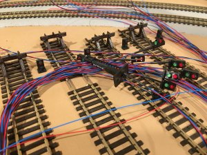
The board will be 6x4 inches and will be installed in areas with multiple switched where signaling in desired. Some usage examples would be –

1. 10 outputs can drive 5 of 2xLED signals with full 4 states (green; red; green+red; all off) based on 12 sensors input. Station enter/exit would be example of that usage.
2. 10 outputs and 8 inverts can drive 8 2xLED signals with 2 states (read or green) plus one 4 state signal. Yards would be example of that usage.
3. Outputs can be connected to 3xLED signals if desired and same physical sensor can be connected to two inputs to provide two different ON->OFF delays to implement yellow.


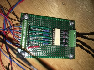
I am still in the process of designing PCB for this and hope to order boards in few weeks.

Any feedback? Would you suggest some other features?

Thanks for reading.

Slava
 
If you are doing it just for fun that's great but such things already exist, are flexible, inexpensive, easy to install, programmable and can interact with one another and/or LocoNet.

The Simple Serial Bus products from:

http://www.rr-cirkits.com/

Have fun.
 
I agree that I am doing this for fun just like the rest of my model railroad. It is an opportunity for me to try and learn new things and good excuse to buy new tools. While building my benchwork I’ve played enough with table saw/jig saw/router and broom, so now I want to play with electronics/voltmeter and soldering iron.

I do think though that it also has practical value, I did not find a board that can support various sensor types and drive 10-20 LEDs. If I missed it I’d be curious to know what it is.

I wanted a board that I can mount under layout in the place of interest and connect all required wires to it – track voltage form frogs/current sensor/photo sensor and signal’s LED. I also wanted to have it working in isolation so I don’t have to connect it to other board/controller or PC to minimize wiring and cost. I just want to connect it to 5v and have my signals work according to the sensors. The board I am designing will have an extension socket that will provide sensor’s inputs and LED’s output so hopefully I’ll be able to design daughter board in the future if I need to connect it to some bus or other devices.

On the cost side I’ve build signals that cost me less that $2-3 and photo sensor should be also under $3.

Previously I’ve build a simple circuit that detects DCC power on my staging yard that uses power routing so I can see route. That board also cost me ~$10 in materials and I am quite happy with it, I can see the route and don’t need a control panel.

Not trying to convince anyone that this is the right direction to follow, I am just sharing. After all – some folks are scratch building track/switches and structures, why not build electronics :).

I’ve placed an order for PCBs yesterday, will see in few weeks if that works out or not.

Slava
 

Attachments

  • IMG_1374.jpg
    IMG_1374.jpg
    299.2 KB · Views: 148
  • IMG_1377.jpg
    IMG_1377.jpg
    323.3 KB · Views: 157
Eventually I’ve decided to build my own circuit board that will take various sensors inputs and provide outputs for LED signals. It is a good exercise and at the end I should have inexpensive solution for what I need.

The Pacific Southern is a large layout that is fully signaled and operates weekly. The owner is a retired engineer and developed a PC program that uses RS-485 to communicate with I/O boards (similar to C/MRI and what you're proposing) scattered throughout the layout to monitor and control turnout position, monitor block occupancy and control signals through a graphical interface of the layout.

He loaned me a book, Railroad Operation and Railway Signaling that describes automated signaling systems used on railroads which seems like you're trying to develop. I had a hard time following the logic for some of the circuits, especially when they were dependent on train direction.

Have you thought thru the logic required for what you're proposing, considering train direction?
 
My layout is not large – 10x16 ft in HO. I don’t have dispatcher’s room or control panel. Instead I’d like to be able to switch routes using throttle or by hand and have signals display route information and occupancy accordingly. All signals decisions could be done locally using nearby sensors and I did not feel a need to connect them to common bus and drive signals from some central point. Also signals will be my control panel on the layout, so I can look and understand the route and/or occupancy.


> Have you thought thru the logic required for what you're proposing, considering train direction?
That is a good point, I did not think about detecting train direction. My layout has double main so that is not required. Thinking more about direction detection I think that would be possible with the board I am building. In short that will require 2 sensors (photo or current sensors) and in addition to 2 sensors’s inputs it would require 2 outputs to be connected back to 2 other sensor inputs for feedback.


Long story - the board will support 12 physical sensors inputs, each sensor input can be sensing switch direction, track current or reflective photo sensor. Then data from physical sensor Sp is transformed to intermittent state Si that adds about 0.2 seconds delay for on->off and off->on state transitions to avoid glitches. Then Si is transformed into internal state Sd that adds on->off delay to Si signal. Delay is adjustable per sensor with potentiometer from 0.5 to 60 seconds. That delay is mainly for current and photo sensors. 12 of Sd are connected reprogrammable IC that has 10 logical outputs. Each of the outputs can be programmed to be any logical function of Sd1 … Sd12 with programmer device. Outputs will then be connected to LEDs.

To detect train direction I’d have to do the following –
1. Connect sensor 1 to Sp1
2. Connect sensor 2 to Sp2
3. Set on->off delay on Sd1 and Sd2 to 0.5 second
4. Set on->off delay on Sd3 and Sd4 to desired delay for direction detection, say 30 seconds
5. Connect output O1 back to Sp3, O2 back to Sp4
6. Program O1 = (Sd1 and ~Sd2 and ~Sd4) or (Sd3 and (Sd1 or Sd2))
7. Program O2 = (Sd2 and ~Sd1 and ~Sd3) or (Sd4 and (Sd1 or Sd2))

Sd3 should be on when train is detected from Sp1->Sp2 and 30 seconds after train clears both sensors.
Sd4 should be on when train is detected from Sp2->Sp1 and 30 seconds after train clears both sensors.
Sd3 and Sd4 could then be used as inputs to program other outputs O3 … O10

O1 is on when we sense direction Sp1->Sp2 and then its 30 timer is reset back to 0, in plain English it would be – start direction 1->2 detection when (sensor1 is on and sensor 2 is off and we not sensing direction 2->1) OR we already sensing direction 1->2 (30 seconds has not expired yet) and (Sp1 or Sp2) is on. Hope that makes some sense.


Slava
 
Last edited by a moderator:
Wow! You're doing a great job with your track detection/signaling system! It looks great and seems to work flawlessly. I wouldn't even know where to begin on something like that.
And, I don't mean to alarm you, but did you know your home has been invaded by short people?:eek:


Back
Top