A couple of weeks ago I built a diorama from a Woodland Scenics kit, and was very happy with the results as well as learning a lot. Based on that unexpected success and encouragement from other forum members, I'm going ahead with my first layout in 45 years (is it just me or are there a lot of stories like that here?). This thread is for me to talk out loud to myself (I really need to join a club!) and maybe encourage any other novices out there.

You are using an out of date browser. It may not display this or other websites correctly.
You should upgrade or use an alternative browser.
You should upgrade or use an alternative browser.
A Beginner's Journey Pt 2
- Thread starter Jacob Z
- Start date
-
- Tags
- beginner layout build
ModelRailroadForums.com is a free Model Railroad Discussion Forum and photo gallery. We cover all scales and sizes of model railroads. Online since 2002, it's one of the oldest and largest model railroad forums on the web. Whether you're a master model railroader or just getting started, you'll find something of interest here.


Will be following along for sure!

")

add a water area which required a bridge for a train to traverse it.

Purposely kept the bridge small so it would not be a prominent feature on the layout. Also, having a bridge with no
overhead features made for easier track cleaning. The water area to the right of the bridge doesn't show very well
in this photo. Just below the area where there are 2 figures on the walkway in front of the building, there is a culvert
that delivers water to the area. The scene takes up a nominal amount of layout space and justifies the existence of the
bridge.

Affiliate Disclosure: We may receive a commision from some of the links and ads shown on this website (Learn More Here)
catnippertom
That Oregon Guy
Fellow novice here! Excited to follow the layout journey. It's all about learning from doing and from the experts on this forum. Have fun!
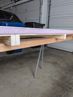
My benchwork is almost complete. The outer frame is 4x1 pine, the cross-supports are 2x1 pine, topped with 1/4" plywood and 1" insulation foam. The plywood is glued and screwed - that's probably overkill, but it didn't take long. The insulation foam is glued down with foam adhesive. Nothing very original in all that.
One thing I'm doing that might be unusual is that I'm building the frame around the plywood. The reason for that is that I wanted to have a lip around the layout because (a) I think it looks more finished and (b) it will be something to anchor plaster cloth to. However, I don't trust the cuts of the plywood or cross members to be precise (I'm not great at woodwork); so it makes sense to fit the frame around the plywood and foam rather than try to cut the plywood to precisely fit the frame.
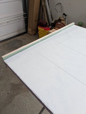
I'm going to paint the foam green so that if there's any gaps in grass, foliage, or other coverage, green will show through, not pink. In these shots, the short sides are on, and the long sides will go on after I have painted the foam (it has been primed here).
The size of the layout is 32"x64", which I could cover with two 2'x4' sheets with one rip and one cut. The layout is going to be N gauge, and 32" gives me a bit more room for curves than 24" while being just narrow enough I can reach across. It also made it easier to cut the foam down to size: the sheet I bought was pre-scored at 16 and 32 inches. The crosscut was easier than I expected it to be. It turns out foam handles very easily. Finally, I carved down the rough edge to precisely match the plywood with a tool whose name I don't know, it's about the size and shape of a hand plane, but the bottom surface is like an industrial-grade cheese grater. Anybody know what that's called? Anyway, it turned out to be perfect for making fine adjustments to the foam.
Overall, given my absence of woodworking skill and experience, and never having worked with foam before, I'm happy with how it looks.
Next up: finish painting the foam surface; add the long sides to the frame and glue and screw them to the cross-supports; and then grout any gaps between the frame and the foam.
One thing I'm doing that might be unusual is that I'm building the frame around the plywood. The reason for that is that I wanted to have a lip around the layout because (a) I think it looks more finished and (b) it will be something to anchor plaster cloth to. However, I don't trust the cuts of the plywood or cross members to be precise (I'm not great at woodwork); so it makes sense to fit the frame around the plywood and foam rather than try to cut the plywood to precisely fit the frame.
I'm going to paint the foam green so that if there's any gaps in grass, foliage, or other coverage, green will show through, not pink. In these shots, the short sides are on, and the long sides will go on after I have painted the foam (it has been primed here).
The size of the layout is 32"x64", which I could cover with two 2'x4' sheets with one rip and one cut. The layout is going to be N gauge, and 32" gives me a bit more room for curves than 24" while being just narrow enough I can reach across. It also made it easier to cut the foam down to size: the sheet I bought was pre-scored at 16 and 32 inches. The crosscut was easier than I expected it to be. It turns out foam handles very easily. Finally, I carved down the rough edge to precisely match the plywood with a tool whose name I don't know, it's about the size and shape of a hand plane, but the bottom surface is like an industrial-grade cheese grater. Anybody know what that's called? Anyway, it turned out to be perfect for making fine adjustments to the foam.
Overall, given my absence of woodworking skill and experience, and never having worked with foam before, I'm happy with how it looks.
Next up: finish painting the foam surface; add the long sides to the frame and glue and screw them to the cross-supports; and then grout any gaps between the frame and the foam.
Attachments
migalyto
Well-Known Member
That's what we like to hear!I'm going ahead with my first layout in 45 years
Will be following along for sure!
With the base almost done and my order of foam underlay arriving by the end of the week, I now have to commit to a track plan. I want to avoid an 'obvious loop', but I also don't want an end-to-end run: I want to be able to futz around in the yard while another train runs continuously. And I don't want a figure 8 with a crossover in the middle because reasons.
My thought for a while has been a dogbone, but folded over on itself with one of the endloops raised above the other (draft 5 below). That would give me a really long continuous run and also some verticality. The lower endloop would be almost entirely hidden under a hillside.
But there is another part of me that is saying I am over-complicating things and I should do something much simpler, like the other plan here (draft 2 below).
In both cases, the big blank space in the middle would have various industries and sidings and so on.
Thoughts, anybody?
Attachments
catnippertom
That Oregon Guy
If you go with draft 2, my one suggestion is to consider swapping where the track passes over one another. It could lead to some sightline issues on the layout. Unless that is something that you are looking for then by all means ignore me.
Do you mean flip the whole thing over so that the crossover is at the back? Or something else entirely? Thanks.If you go with draft 2, my one suggestion is to consider swapping where the track passes over one another. It could lead to some sightline issues on the layout. Unless that is something that you are looking for then by all means ignore me.
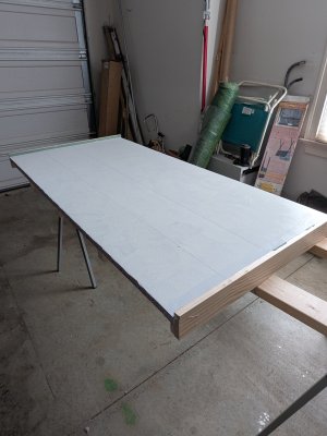
The box for the railway is finished. It's not as square as I would have liked, but it is fit for purpose. (I thought I did everything I could to get it square, but apparently I'm still learning...) I'm going to postpone staining and varnishing the outside until much later because I am sure I will get glue, paint, etc. all over it. The next time you see it, it should be out of the garage and in its permanent home (spare bedroom).

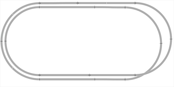
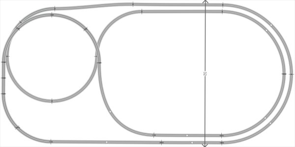
After a lot of thought, I've decided to go with a simpler plan that still gives me a decently long continuous run - plan below. (Ignore the "stub" turnout, that's for whatever industries or shunting yard I decide to put in the middle.) This plan eliminates the really tight curves the other one would have required, and also makes the inclines easier to accommodate. An area roughly 16x16 in the top left will be elevated, hiding where the upper track crosses over the lower.
Next up: transferring the plan to the baseboard.
ETA: I really wanted a truss (or other) bridge, but there is nowhere to naturally include one, that I can see. Unless I have a road pass underneath the incline towards the bottom of the track, and a level crossing for it to cross the at-grade track at the very bottom, before disappearing "off-stage".
Last edited:
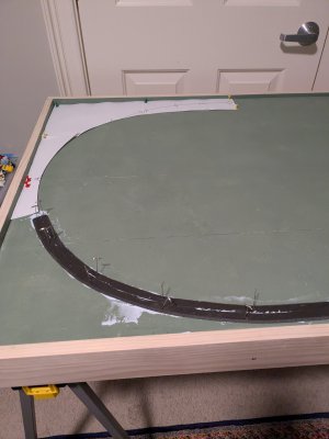
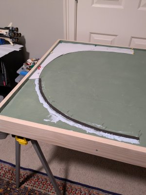
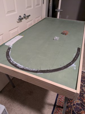
I made a start on laying the foam underlay (Woodland Scenics) and overall I'm pleased with how well it went. I realize that this is a very basic thing for experienced modelers, but I was worried about how I would accurately transfer the layout to the board. After some futzing and a lot of thought, I arrived at a multistep process (pictures attached).
I forgot to weight down the underlay overnight, but checking in the morning it seems absolutely solid, so I will probably continue to do that. For the track, I will be more diligent. I also discovered that the adhesive does not dry clear, so I'll need to be neater if I use it anywhere that might be seen.
I also realized that I should probably have started with the turnout at the top left and worked backwards from there, but I forgive myself because this was an experiment and I had no idea what I was doing")
*T-pins were $2.99 for a pack of 40 from Hobby Lobby, so I bought two, which is way more than I will ever need in this lifetime. I've seen the same thing with a much fancier name and higher price in modeling supply stores online. For example, WS sells "foam pins" that are the exact same thing except priced 25% higher, plus shipping. One of the things I have quickly learned is that anything generic (pins, glues, etc.) can usually be bought cheaper at a DIY store or hobby store than a railroad model specialist store.
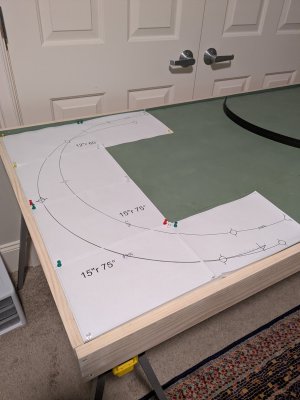
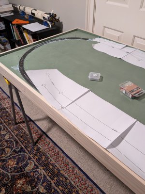
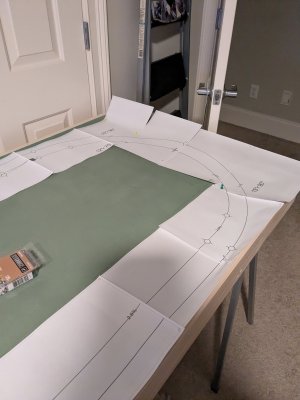
- Print the design full size from Anyrail, showing only the centerlines and slopes.
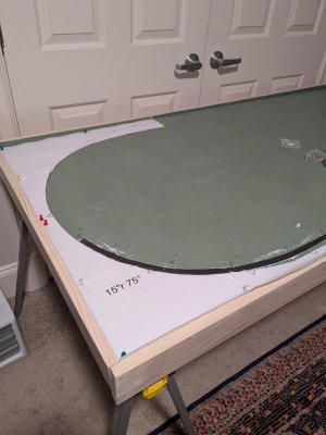
- Pin the design in place to make sure everything is okay and I didn't screw up anything major (like putting the wrong baseboard dimensions into Anyrail). Note that I only did a small section to begin with as I figured out the process, and I'm working in an area that will mainly be covered by the upper layer eventually.
- Remove a sheet at a time to my workbench, carefully cut along the centerline with a hobby knife to create a template, and put it back in place.
- Carefully divide the underlay down the centerline. I'm working in 21" pieces because that's the longest metal straightedge I have, and my hands are not steady enough to freehand the cuts.
- Apply glue (I'm using the same foamboard construction adhesive I used to glue down the foamboard to the plywood), then position the inner curve of the underlay, pinning in place*. I discovered here it was a good thing I was working in small sections as that adhesive gets tacky extremely quickly and sets quite fast too.
- Remove the paper template, apply adhesive again, and position and pin the outer curve.
- Rinse, repeat.
I forgot to weight down the underlay overnight, but checking in the morning it seems absolutely solid, so I will probably continue to do that. For the track, I will be more diligent. I also discovered that the adhesive does not dry clear, so I'll need to be neater if I use it anywhere that might be seen.
I also realized that I should probably have started with the turnout at the top left and worked backwards from there, but I forgive myself because this was an experiment and I had no idea what I was doing
*T-pins were $2.99 for a pack of 40 from Hobby Lobby, so I bought two, which is way more than I will ever need in this lifetime. I've seen the same thing with a much fancier name and higher price in modeling supply stores online. For example, WS sells "foam pins" that are the exact same thing except priced 25% higher, plus shipping. One of the things I have quickly learned is that anything generic (pins, glues, etc.) can usually be bought cheaper at a DIY store or hobby store than a railroad model specialist store.
Attachments
-
 PXL_20250118_230116630.jpg316.7 KB · Views: 153
 -
 PXL_20250118_223016483.jpg370.8 KB · Views: 151
 -
 PXL_20250118_225522961.jpg400 KB · Views: 153
 -
 PXL_20250118_225912750.jpg426.9 KB · Views: 154
 -
 PXL_20250118_232020985.jpg411.7 KB · Views: 153
 -
 PXL_20250119_115750180.jpg554.3 KB · Views: 151
 -
 PXL_20250119_115754185.jpg331.3 KB · Views: 153
Last edited:
Now I'm trying to figure out what to do about underlay for the turnouts that come next, and for the industries and yard that I have yet to figure out in detail. I am tempted to just get a sheet of underlay for the whole area to give that less-ballasted look, and also to avoid having to transition in height from a main line on underlay to sidings without.
Also having "fun" trying to figure out how to trim the underlay for the turnouts from the main line - or whether to just include those in the area covered by the sheet (which feels a bit like cheating...)
Also having "fun" trying to figure out how to trim the underlay for the turnouts from the main line - or whether to just include those in the area covered by the sheet (which feels a bit like cheating...)
KB02
Well-Known Member
No such thing... as long as it works.(which feels a bit like cheating...)
OK, I have figured out the turnouts. I printed out the relevant part of the layout from Anyrail, this time including both the roadbed and the centerline. From that I was able to cut out a template for the turnoff part of the turnout so that I could accurately cut the angle for it to join the straight part. I'm looking forward to moving ahead with the rest of the track laying as soon as my inclines arrive.
Also I have decided that the insulation foam is a very useful thing even aside from its sound-deadening qualities. It is very handy to be able to pin sheets of paper, underlay, and other things in place.
Also I have decided that the insulation foam is a very useful thing even aside from its sound-deadening qualities. It is very handy to be able to pin sheets of paper, underlay, and other things in place.
Last edited:
logandsawman
Northern Pacific history enthusiast
I heard it called a cheese grater. I use one for auto body work, to shave down body filler before it is totally solid.
Also, I found out what the tool I used to carve down the foamboard edge is called. Apparently, it's a former - and it's possible it was actually designed for forming foam boards
Minor update: I have decided to go with the B&O because it's one of the few names that gives me a decent selection of transition-era steam as well as a switcher - probably diesel, both because of availability and because it seems reasonably prototypical of that era to be running steam on the mail line and diesel in the yard (yes?).
Also I have decided to call my layout Pointy Rocks because it is loosely inspired by the geography around Point of Rocks where the B&O followed a water gap through a ridge of Catoctin Mountain, later supplemented with a tunnel. Nearby Brunswick was an important junction on the B&O. If I get really ambitious I might eventually attempt a version of the distinctive Point of Rocks station.

Also I have decided to call my layout Pointy Rocks because it is loosely inspired by the geography around Point of Rocks where the B&O followed a water gap through a ridge of Catoctin Mountain, later supplemented with a tunnel. Nearby Brunswick was an important junction on the B&O. If I get really ambitious I might eventually attempt a version of the distinctive Point of Rocks station.
shortwrench
Well-Known Member
My layout is similar to yours; no elevation but wanted a bridge. Decided to carve out a depression in the foam andAfter a lot of thought, I've decided to go with a simpler plan that still gives me a decently long continuous run - plan below. (Ignore the "stub" turnout, that's for whatever industries or shunting yard I decide to put in the middle.) This plan eliminates the really tight curves the other one would have required, and also makes the inclines easier to accommodate. An area roughly 16x16 in the top left will be elevated, hiding where the upper track crosses over the lower.
Next up: transferring the plan to the baseboard.
ETA: I really wanted a truss (or other) bridge, but there is nowhere to naturally include one, that I can see. Unless I have a road pass underneath the incline towards the bottom of the track, and a level crossing for it to cross the at-grade track at the very bottom, before disappearing "off-stage".
View attachment 209291
add a water area which required a bridge for a train to traverse it.
Purposely kept the bridge small so it would not be a prominent feature on the layout. Also, having a bridge with no
overhead features made for easier track cleaning. The water area to the right of the bridge doesn't show very well
in this photo. Just below the area where there are 2 figures on the walkway in front of the building, there is a culvert
that delivers water to the area. The scene takes up a nominal amount of layout space and justifies the existence of the
bridge.
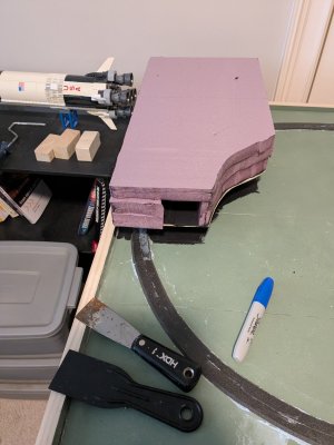
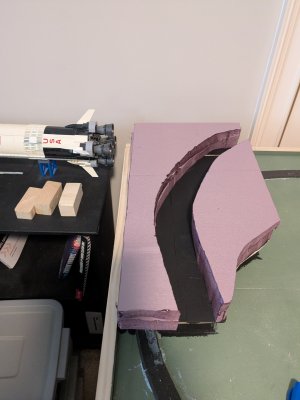
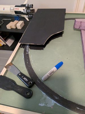
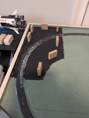
Dry-fitting the raised area. Both the lower track and the elevated track go through the mountain. I haven't decided yet how high it will get altogether. Currently at about a scale 75'
This is my first time working with foamboard for scenery and a hot knife. It was pretty straightforward for a rough cut like these, but whoever did the pictures on the box has either a lot more skill or a lot more practice than me.
Once everything is glued in place I will carve it into a hillside with the hot wire cutter.
Attachments
Welp, that was absolutely brutal. Central Valley 150ft pratt truss bridge. Now I need to clean up the glue spots with the world's smallest piece of steel wool, then paint it. I have no idea how people with normal sized hands do this (Mine are really small: nobody, not even the rain, has such small hands).
I'm still not sure whether this is going on the layout, and probably won't decide until I see how the painting turns out. Maybe I will just build a diorama around it...


I'm still not sure whether this is going on the layout, and probably won't decide until I see how the painting turns out. Maybe I will just build a diorama around it...
Last edited:
Affiliate Disclosure: We may receive a commision from some of the links and ads shown on this website (Learn More Here)