Servo jitter with long leads


rcav8rToo

New Member
I am controlling my turnouts with those cheapie 9 gram servos. When I set the throws with a device I made to show me the servo angle in real time, the servo works well.
When I hook them up to my DCC controller using the same extension that I used to get the servo angle, the servo shutters wildly and it is not at all controllable. If I remove the extension and plug directly into the DCC controller, all is well. The servo extension is one I made using supplies I use to make them for my R/C airplanes. Connectors are gold plated, and wire is 22 gauge high strand count. I also make these for flying buddies and have never had a failure myself or have heard of one from my buddies, so I am fairly confident that the extension is OK . I even tried 2 other ones with the same results. Extensions are 24 inches. I will need a few longer ones for other turnouts.

I also tried some higher quality servos (Hitech HS81, HS65, Futaba 3001, etc) and they all work just fine with the extension in place. Common denominator appears to be these 9Gram servos. I tried a few of them, and they all behave the same.

I already 3D printed all the servo mounts, and at a dollar or so a piece (as opposed to $15 or so) I really would like to use these servos. There are also a few places I can not fit larger servos.

Anyone else experience this, or any suggestions?

Thanks
Dave
 
THANKS
Yea, I was going to make up an extension with twisted wires tonight after work. I have heard of that working, but not known of anyone actually doing it. Where would the ferrite beads go? One wrap on the signal line near the servo , or DCC encoder, or both?
 
I don't know if putting more cap's on the DCC line would be the thing to do; especially if you have many servos that need connected. I would be interested in seeing the DCC waveform with nothing connected, then the errant servo vs a good one. Same thing for putting a torriod or bead inline - what does the DCC line look like first?
 
I don't believe it is the DCC line. It is DCC++ EX on an Arduino branded MEG with an Arduino branded motor controller. Didn't want to take a chance on clones for this.

That, and more importantly, the issue occurs when it is not using DCC. I am using MarDec (https://www.arcomora.com/mardec/) as the DCC controller and it is occurring in programming mode. When not moving or programming a servo it detaches the servo. No chatter on a slightly stalled servo.

To program it, you USB attach the UNO and program from a puTTY session to the UNO. DCC not in the picture at this point.

As soon as I go to program mode for the port it is connected to, the SG90 servo twitches wildly (when using the extension) . I have tried other ports. In programming mode you press 9 to set it to mid travel, C to move it one way a few degrees (to start, you can increase/decrease this with the +- keys) and then C again to move the opposite direction. With the SG90 and no extension and with the other servos and extensions, it does exactly that. Here is where you also assign the port a DCC address (A key)
After that, you put it in run mode. That is when you can control with DCC., and the puTTY session is no longer needed. I never get that far with the SG90 and extension as I immediately unplug it as even after a few brief seconds the motor is warm. All other scenarios it behaves as expected.


SG90======Extension=====DCC Shield/UNO Does not work
Any other servo=======Extension===DCCShield/UNO Works great
SG90=======DCCShield/UNO Works great.

THANKS
Dave
 
Thanks, was wondering about DCC but that is what I read. Haven't played with DCC++Ex but have played with Arduino's. All the cheapo servo's do this? Is there a pull up or some other shorting bar that tells the servo what it is being used with? Sounds pretty weird if all do the same thing. Can you program without the UNO just to get stuff running?
 
Being a newbie, I have nothing to reference , but the DCC++ EX works great for me. SUPER easy to get going. Not sure the non clones are needed, but I felt better using them for this. Connects to JMRI very easily.
I can't say all the cheapo servos do this, but so far everyone I tried does. (about 5). None of the good servos do this and I tried all the way from micro to high torque standard size ones. I do have some older cheapo 9 gram servos I pulled from R/C planes where they worked great, but the plastic bearing were wobbly after a lot of use so I replaced them; and they too did this. Granted they were in small foamy type planes, so no extension needed.
Not sure what you mean by a pull up or shorting bar. The Uno ports to have internal pull up resisters. Maybe add another?

I do have the layout partially programmed using another Mega and a sensor shield using toggle switches to throw the turnouts . Long story short this is SUPPOSED to work with CMRI (Within JMRI) but I never had luck with more than 2 servos working at a time., so I went the manual toggle switch route. All work fine with the mechanical switches. Presently it is a mess and really need to make a proper control panel if I need to go this route. As I am typing this I realized that it is working with the cheapo servos and extensions, but the PCA9685 is driving them, not the UNO itself as in my DCC setup. Hummm? My main goal is to control the turnouts via JMRI panel pro, so once I learned I could control via DCC inexpensively, I decided to go this route. And it does work great. I can control 5 servos ( so far) from JMRI using the DCC shield. But they are not the servos under the bench for the turnouts. Just on top as tests.

Below is a kindergarten drawing of how the servos are attached to the DCCshield.

Thanks
Dave
9gServos.png
 
What is powering the servo's? Where does the +5V line in your drawing come from? I sincerely hope your "-5" is actually a ground, or you are applying 10V to the servos. Also, I hope you are not powering the servos from the Arduino. I'm not sure about that shield, but a lot of them that run servos have a jumper so you can select power from an external 5V input to the shield.
 
Dave - maybe a st00pid question: What hardware comm is the UNO using to talk with the 9g? If I2C or Twi, comm speed could be causing grief. Even with CLK/MISO/MOSI there are certain parameters that need to be met. Can you slow down the UNO in that respect? The cheapo servo might not have the same input impedance as the better ones due to cost cutting and slowing it down might do the trick. Had this problem with Twi as the slave CK speed had to be at least 16 times the master's comm speed. May be a shot in the dark.

[edit] just re-read your last. The 9685 is causing the problem then and it works with with other servo's. Maybe some setup there needs to happen.
 
@diesel; I have a separate 5V supply coming form a dedicated Buck board that powers the servos. Servos indeed only have 5V applied to them and in the proper polarity. I did verify this with a VOM before ever connecting a servo. The Negative (ground) of the DCC shield is connected to the negative for the power buss of the servos as they need signal and the same ground to work. So in effect this is isolated like setting the jumper on other shields.

@ctclibby; When you say comm for the UNO, I am guessing that you mean the pins connected to the servos. I am guessing they are using the standard digital output, not something like I2C. I am using a Arcomora which is an Arduino sketch where you never really see the sketch per say. You configure with a menu via a putty session. Pretty slick actually.
You mention impedance. Had not thought of that, but I think you are on to something as the impedance would change with the longer extension, and that is what is making it unhappy. Wonder if these is an op amp circuit or something I could use. Or a passive filter?

When using the PCA9685 and extensions it works. I am pretty sure if creates the PWM differently than the UNO. (not sure if that is the case or how if it is, but that would make sense) With the DCC Shield, basically the pin on the UNO is sending the PWM to the servo.
 
Any way you can look at the signal(s) going to the servo? If it is a two wire ( +logic, gnd ) you may be able to kludge something in. Passive filter would probably make it worse as you would be adding impedance.
 
Try putting a 100uF capacitor directly across the servo GND and 5V, at the end of the extension. It's more likely to be a power issue than a signal issue, the servo PWM is too slow to be affected much by cable layout, to a great extent.
 
FIXED.
I wanted to make sure it really was fixed before I posted. I tested a few different times on the bench and then mounted on the layout and got 5 of the 10 servos working today including working from JMRI. Will do some more tonight.

A 4.7K pullup resister was the fix. I placed it between ground and signal on the end of the servo connector. Jitters like mad with out it, and works normally with it. Removed and it jittered again. Placed back in, and worked normally.
I also added a 100uf Cap between the + and - 5V on the breakout board I made for the servo connectors. Can't say if it helps, but figured it couldn't hurt as the lead to the breakout board is much longer to where it lives under the layout as opposed to on the bench when I was testing.

THANKS to all who assisted.
Dave


ServoResister.jpg


Arcomora.jpg
 
It looks like there is a problem with the impedance of the device generating the servo pulses, adding the resistor lowers the impedance. This needs to be a low impedance in order to quench interference on the signal line to the servo (some servos have an excessively high input impedance!) Something else that might help is using digital servos rather than analogue ones, try using SG92R instead and see how you get on. The SG92R has built in signal filtering that should filter out stray pulses.
 
Glad you got it working.
Schematic is here > pca9685 This is for the Adafriut board, yours should be close. Board puts out 25mA per channel; 400mA total, so not a lot to play with. You may see some issues as you add more servo's to the board. Oh, and comm to the board is I2C ( Twi for Atmel speak ).
 
@Suzie;
I do have some micro Digital servos ordered. Should be here today. EMAX ES9051 (4.1g) Digital Nylon Gear Servo
I plan on using these where I have really long runs. Most of my points are concentrated in 2 areas. I have an Arcomora UNO for each area But there are 2 points that are about 8 foot from the closest Arcomora. Hoping the digital servos will do the trick there. I haven't even tested the SG90s with runs that long.

@ctclibby ;
Thanks. The Uno is driving the servos, and there is a separate 1.2 Amp 5V supply with auto reset circuit breaker for the servos. The servos detach from the Uno when not moving, which is a really nice feature. I can set the points a little tight and not have to worry about a stalled servo. I only have 2 instances where more than one servo will be moving at a time.
I had been previously using the PCA9685, but abandoned that as I had all sorts of problems getting it to interface with JMRI via CMRI. Interestingly enough that is where the SG90 servos worked with no issues. Worked well with manual switches, but not via JMRI. The current setup is using DCC addressing for the ports and is working very well in JMRI.

FWIW, here is the system I am currently using and now that I am using the dropping resister on the SG90s it is working great.

Thanks
Dave
 
Hello, I did not see these interesting posts in time, but maybe my fellows in the club did.
We have the same kind of problems on the N network of the club.
It is fitted with ESU eCos running DCC, Train Controller on top, and Arcomora devices, of which Mardec 's for the switches and frogs.
The servo's are cheap ones (SG90). The Mardec signal is not permanent.

From time to time, when a locomotive runs close to the switches, some servo goes fully on one side, inducing short circuit and train derailment.
Not every loc has the same chance of giving a prob. Some do worse than others.
The DCC signals were investigated with tracer software, and no problem was found.
An oscilloscope showed a lot of small spikes, and some big short spikes of almost 3 or 4V !

For now, we have the following solutions installed (one solution on one servo, to be able to look at the best), and the problems disappeared. We are still investigating.
- a diode (and resistor) in series with the servo control signal, which reduces the signal level.
- a low pass filter (1K in series, 100 nF in parallel)
We will also try a shielded cable for another servo. Our data signals run separately, power and ground are gathered.

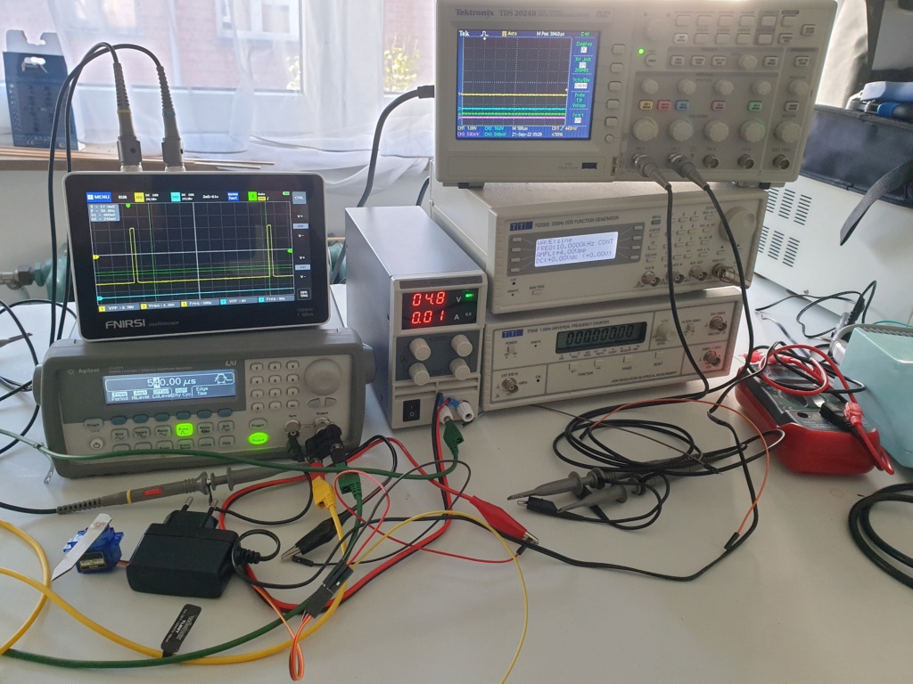
I made some lab experiments with short pulses (simulating data spikes), as can be seen in the following videos:
- the servo does not react to pulses under 400 microseconds
- if the servo is set around the middle (1500 usec), then receives no data (as our Mardec's are set) and the servo then gets a spike of about 400 usec, it will suddenly do a fast move, like we get on the switches.
But this is only lab testing.

20220912.jpg


Will keep you informed of the progresses.

Phil.

The videos:


Last edited:
Phil: You say the data signals run separately. That the PWM? Do you have it twisted with power and ground? I would start looking at the signal(s) to the servo. Use a current probe to monitor the PWM width(s), regular probe for power and ground lines to the servo. If you catch the glitch, does the power drop just before? How about ground. Look at the input of the servo controller also. Any funny business there when the glitch happens? The 400uS - have you captured that yet or is this blind testing that you determined something less will not twist the servo.

Could be that the servo controller is causing the errant spike. Did you write the code for it? If so, you might be sending something that you don't want to send. Also, how long from reset until you initialize the port for the PWM? Ya, you have to cycle count or if you have an extra port pin, put a short pulse on it to use as a trigger during the initialization.

In certain circumstances a DCC controlled engine could be a big EMI radiator although I have trouble with it causing spikes large enough to twist the servo. Oh, I say the current probe for the PWM signal as there is no insertion impedance as there is no physical connection. Sure, the tiny coils in the current probe will give you *some* impedance but it should be a lot less than the physical connection. ( the old 'it does not work until I put my scope in the circuit' scenario ).

Have fun playing!

Later
 
Thanks for your quick reply. I will try to answer or comment some of the items:

- data signal: I mean the pulse of 1000 to 2000 microsecs at approx 50Hz repetition, issued by the Arduino of the Mardec. Not really a PWM, but I have seen that an AnalogWrite is used in the code of the MardeC

- Twisted? No, not even in parallel, one wire running completely alone (it is a real "antenna" ;) )

- Current probe? No probe for low currents available. Should I just use a low value series resistor?
I have a 4 channel Tek, so I could monitor data, power and ground.
Problem is we have to reproduce the original setup to see the problems, but I will remember the suggestion.

- The glitches can be seen with an approximative guess of width, but could not yet be captured, as there are a number of glitches, and not all fire the servo.

- Servo controller: what do you mean ? The Arduino of the Mardec? The electronics inside the servo?

- We use the standard Arduino code of Arcomora (Mardec is the decoder unit in the Arcomora family). I am not ready to code that type of control software. I have written a small "DCC sniffer" or servo controllers, but Mardec has a lot of functions...
And we are highly confident that is not the cause, but who knows? I keep this possibility open.

- Do you mean inputting a pulse on a free Arduino pin to check the reaction?

- I agree: the "DCC controlled engines" are big spikes emitters, some more than others, and this is reproductible ( e.g. one engine gives the prob once on 10 runs , another one once on 2 runs)

Will continue in order to get a stable solution, thanks again

Phil.


Back
Top