ModelRailroadForums.com is a free Model Railroad Discussion Forum and photo gallery. We cover all scales and sizes of model railroads. Online since 2002, it's one of the oldest and largest model railroad forums on the web. Whether you're a master model railroader or just getting started, you'll find something of interest here.
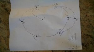
blocks are solid lines.
Signals are off to the sides (Direction it faces is shown with the arrow)
Here are my questions:
Is this correct? Are the signals in the right places?
Assuming this layout how many lights would each signal get? I'm guessing twos where there are turnouts and 1 at the midpoints?
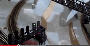
In one of the videos it had three lights stacked, top was high speed, middle was med, bottom was slow. Do I need to worry about this, do these signals tell you anything about turnouts or are they just speed related?
Any other stuff I should know? Letters (upper and lower) are there so it's easy to refer to the diagram.
Exactly what kind of signals you have, and where, depends on the time period you're modeling, the specific railroad, and the traffic. Some newer lines, like the Amtrak-Metro North New York-Albany line, just have cab signals and no visible signals on the railroad itself. So you'll need to give us more info on what you're meaning to represent.
Yes, like that. I'm going to have block detection and turnout position. I'm writing my own software to control it which you can switch to manual or auto I just want to make sure I get everything right. From what I understand the light is green if two blocks in front are open, yellow if only the next block and red if the next block is occupied. My question comes in how to handle switches/turnouts. Say I have three blocks and there is a turnout between 2 and 3. Only one block on the turnout is occupied so how would I relay this down track? Do I need multiple sets of lights to indicate what each track on the turnout has?
There are 2 turnouts for that bridge thus 2 sets of signals. Starting with post 71 for all the details on the signals on this little layout, you may want to read over the thread at: http://www.modeltrainforum.com/showthread.php?t=14852&page=8
most signals are on the right side of the track facing the engineer. Your general placement on your drawing is good, some should be moved to the right side of the track at the turnouts, others are fine. Single heads are generally your block signals like on your left side, at turnouts they are interlocking signals. Facing point switch signals usually will have 2 heads, Green/red straight, Red/green turn. Differrent railroads deal with signals differrently, but thats a good basic. Placing a signal on the left side is dependent on the circumstance, some may just put one post up and 2 heads facing opposite. 4 heads above seem wacky to me but the layout prolly has its reasons.
Generally yes, the intermediate signals should be about a train length apart.
The one I would question is the spur breaking off the top of the loop. Normally a spur wouldn't be signaled and the signals would not be related to the switch (other than causing a red block if the switch was open).
2. Assuming this layout how many lights would each signal get? I'm guessing twos where there are turnouts and 1 at the midpoints?
The signal at the points end of siding or multiple main track switches would have two heads. Intermediates and signals on the frog ends of siding and multiple main track switches would have 1 head. Of course if you are following a specific prototype, their practice prevails.
3. In one of the videos it had three lights stacked, top was high speed, middle was med, bottom was slow. Do I need to worry about this, do these signals tell you anything about turnouts or are they just speed related?
That's only true if you are modeling the 1800's or don't know much about signals. The various combinations of colored lights are specific to each signal indication and one can't make universal generalizations based on the number of heads. There are two different types of signal indications, "speed" signals and "route" signals. In a route system there are "diverging" aspects, a red over yellow is diverging approach which means the train is going to take the diverging route through the switch, should proceed at the speed of the turnout and has to be prepared to stop at the next signal. On a speed signal railroad the signal would indicate the speed through the turnout and require the train to be prepared to stop a the next signal. With route signals the indications require the crew to know the speed of the turnout (from the timetable) and with speed signals the signal tells the crew what speed to go. Both end up at the same place.
I would pick a railroad to follow, doesn't matter what one, but picking a road or rule book (search for CORA signal rules, GCOR signal rules or NORAC signal rules) will keep your signals consistent.
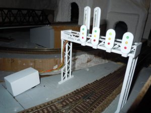
There are 2 turnouts stacked together at this location with the points facing the same direction. Each turnout approaching from the point side has a 3 over 3 signal. The upper signal head is the straight and the lower is for the diverging route.
Well, like you said, this is mainly for your own use/spectator appeal and not prototypical, but this is not really how it works.
The individual heads when you have a signal with multiple vertically stacked heads are not independent from each other. Each head does not correspond to a route, although in a simple situation with only one diverging route it will effectively look this way. You could have a major interlocking with 5 different alternate routes a train approaching on a given track could take, but that train will only have one signal governing it, and it's highly likely that most of those routes will give the exact same indication.
The basic rule for any signaling is one signal <-> one track. Each track has its own signal, and you don't add signals for each switch in the area. Also, signals apply at the point which they are located, so if you're trying to be realistic you wouldn't have a bridge over the middle of a switch like that, you'd have separate signals one either side of the switch. The approaching signal should be in front of the points, and the other signals should all be beyond the clearance point of the tracks coming in to the switch(es).
Your arrangement seems to work for you and that's fine, but my sense of the OP's question is he's trying to figure out how it's actually done on real railroads and that's not it.
You would have a main leading interlock signal telling you the way is clear whatever speed indication not indicating any route, following at the actual turnouts there could be dwarfs indicating route. Each railroad has their way of dealing with signals, the same goes with we modelers, how complicated we want to get. It gets more curious with PRR and N&W position signals, we've had or I have read some good discussions on the N&W email board about signals and the purpose of signals can vary a lot for each individual installation.