Non fluent electrical flow

ModelRailroadForums.com is a free Model Railroad Discussion Forum and photo gallery. We cover all scales and sizes of model railroads. Online since 2002, it's one of the oldest and largest model railroad forums on the web. Whether you're a master model railroader or just getting started, you'll find something of interest here.


After a lengthy time of on again off again work I've finally completed wiring 13 turnouts and feed wires I've developed some issues. All but 1 turn out works. The 1 will hum but doesn't switch. Problem #2: when trying to run an engine I have dead spots (meaning no movement) through out the layout. (Atlas Layout N-8 from Introduction to N Scale Railroading, Book #6. I've insured the plastic joiners are as designed in the layout.
Before climbing under there & checking each splice. Is there an easier way of tracing down the problems?
 

Attachments

  • layout_001.png
    layout_001.png
    5.1 MB · Views: 137
  • layout_000.png
    layout_000.png
    4.9 MB · Views: 130
As for the turnout that hums, double-check the wiring from the electrical switch to the turnout. Make sure nothing is shorting out and the wiring is connected properly. If that checks out, then make sure that the switch machine and/or the turnout points aren't sticking for some reason. If that checks out, then quite possibly the switch machine is bad, and you may want to replace it (or the whole turnout, as the case may be).

For checking dead spots, unhook all 12 block wires from your selectors. Then hook up block #1 wire and see if a loco will go through the entire block. If so, then hook up block #2, and see if the loco will successfully run on both blocks 1 and 2. Keep hooking up block wires one at a time and testing the loco as you go. When you get to a block that doesn't respond, there's a good place to stop and check out all possibilities for errors in wiring at that particular block.

Also, don't forget to check for loose track joiners. Make sure they are all properly slid on to the rails and tight-fitting, as any loose ones can and will stop electrical contact.
 
First, some pics of the 1 turnout would be nice, as there are many different solenoids and motors that operate turnouts.

Second, are you using a common rail? If you are, make sure it's the same rail EVERYWHERE.

Third, what are you running on - dc, or dcc?
If you are dc with blocks, Mixed Freight is right...
I would check that each block switch is "hot" first.

Forth, are you running wired frogs?

One thing, if you hook up a light bulb in series with your common rail connection to your power pack, it will light up when there is a short. It will protect from burn outs while you troubleshoot. Solder your leads right to a old school 1157 turnlight bulb if you want.


First, some pics of the 1 turnout would be nice, as there are many different solenoids and motors that operate turnouts.

Second, are you using a common rail? If you are, make sure it's the same rail EVERYWHERE.

Third, what are you running on - dc, or dcc?
If you are dc with blocks, Mixed Freight is right...
I would check that each block switch is "hot" first.

Forth, are you running wired frogs?

One thing, if you hook up a light bulb in series with your common rail connection to your power pack, it will light up when there is a short. It will protect from burn outs while you troubleshoot. Solder your leads right to a old school 1157 turnlight bulb if you want.
All of my turnouts are Atlas 2701 series. I've checked the common rail and I was very careful to use the same side throughout. Now I need to check that ALL of the rail connections are tight. I have a funny felling I might have gotten sloppy on some of them. BTW I'm using DCC.
Can you give me directions on how to hook up a light bulb in series with your common rail connection to your power pack? Would it be connected to the common wire I already have? I'm still pretty ignorant when it comes to electricity and model RRing. The 1 turnout I'm having trouble with works in 1 direction with the switch but not the other way.
 
Here's the simple thing I did on my DCC layout. I took a multitester, a battery, and some crocodile clips. I disconnected DCC from the rails. A 9V works well because it is easy to clip wires to. I applied power to one section of track. And then I went down the track with the multitester testing for voltage (i.e. continuity) after each track connection. This is a very simple test of physical continuity through your joiners.

If you find a section without continuity, you can either fix the joiners or drop more feeders to power that section. (Actually, you should probably fix the joiners anyway because eventually they will come back to bite you, it turns out.)

I also checked my feeders before hooking to the bus by attaching the battery to the rails and putting the meter on the feeders. Because I have very low confidence in my electrical skills.

By the way, one of the things I discovered in this exercise was that voltage does not drop due to rail resistance anywhere near as fast as I had read. The "feeders every 3 feet rule" is overkill if that is the concern. However, it is probably still a good idea to have feeders on every length of flex track as a hedge against bad connectors.
 
I can get a reading of 12V on the wires from the transformer. But I don't get any reading from the track section that runs my train engine. I know some of you think I'm stupid, but I just don't get it. can someone explain please?
 
I am unable to offer any help here, because I use DC. But my question after reading your posts is why are you using blocks and insulated rail joiners on a DCC layout? Or is that a typo in post #4?
 
I can get a reading of 12V on the wires from the transformer. But I don't get any reading from the track section that runs my train engine. I know some of you think I'm stupid, but I just don't get it. can someone explain please?
First of all, I do not think you are stupid. I am newbie myself, and I have learned tremendously from this forum by admitting my ignorance and being willing to ask for help. And every time I do so, I have been impressed by the way nobody acts like I am stupid for not knowing what they know. (I have an entire thread devoted to the mistakes I have made, hoping other beginners will find it helpful).

If your multimeter is set to AC and you are using HO, you should get something close to 14V when there are no locos on the track, a bit less if there are locos on the track because even if they are not moving, some of the voltage "drops" across the locos.

If you get a reading of zero from a section of track, that means that it is isolated from adjacent sections, i.e. the rail joiners are not making good contact; and the feeders to that section, assuming you have them, are also not making good contact to the rails.

You mentioned that you have isolated blocks, as one normally would with DC power, so I have to ask: is this particular problematic block intentionally isolated from adjacent ones? In that case, it's your feeders. Check them where they connect to the track, and where they connect to your bus. If you still get no reading, something is wrong with your bus.

If you are not using a bus but instead something like a distribution block with wires running , check at the block that the relevant terminals have power.

One unlikely thing you should also check is that you didn't accidentally attach both of the feeder wires to the same side of the bus, i.e. both to the black wire or both to the red wire (or whatever colors you are using.) Normally in DCC that would short out the whole thing, but if this section is electrically isolated, it's possible.

Basically, you need to trace step by step from the rails where you get 0V through each connection all the way back to your transformer, until you find the break, i.e. where you stop getting 12V and start getting 0V. You just have to be systematic about it.

Out of curiosity, how are you wiring your track? A bus with feeders? If so, how are the feeders attached to the bus? What kind of attachments? Or a connector block with wires to each section? There are lots of way to do this, and some are more reliable than others.

So Willie. Are you saying when using DCC I shouldn't use insulated joiners?
Jim

With DCC there is no need to use insulated joiners between blocks. You will need insulated joiners with a reversing loop, because otherwise you are connecting the "red" rail back to the "black" rail, which is a short circuit. And some kinds of turnouts do also need insulators, but I can't provide details because the ones I'm using (Peco Unifrog) do not.
 
So Willie. Are you saying when using DCC I shouldn't use insulated joiners?
Jim
They are normally not needed in DCC layouts except as Jacob indicated in reversing loops. I don't see any reverse sections in the layout diagram that you posted. You can use them if you want, but they are not needed.


OP:

It helps when you tell us what scale you are in. Is it N scale?

IF you are using dcc (and NOT DC), you don't really need insulated rail joints in most places. The exception would be for a reversing loop or wye -- and you don't have one, as per your plan above.

Having said that, one can still insulate track sections in dcc. But in that case, you must insulate BOTH rails at such locations.

Are the Atlas 2701 turnouts power-routing, or are they non-power-routing?
I'm going to take A GUESS that they are non-power-routing (because of the plastic frogs).

Looking at your plan above, WHICH switch is giving you the problems?
If you remove it and replace it with another one, does the replacement switch have the same problem?
(repost the track plan with an arrow showing us the problem switch)

What dcc setup are you using?
 
All of my turnouts are Atlas 2701 series. I've checked the common rail and I was very careful to use the same side throughout. Now I need to check that ALL of the rail connections are tight. I have a funny felling I might have gotten sloppy on some of them. BTW I'm using DCC.
Can you give me directions on how to hook up a light bulb in series with your common rail connection to your power pack? Would it be connected to the common wire I already have? I'm still pretty ignorant when it comes to electricity and model RRing. The 1 turnout I'm having trouble with works in 1 direction with the switch but not the other way.
I don't think you are stupid either...

In a couple of hours, you can get this thing going!!!

All of the other posters are generally correct - for this layout, you do not "need" to use plastic joiners anywhere. You can use them if you want to though. In fact, I want to strongly advise you to have at least two sidings that use them so you can park and power down locos. This way you can use programming track mode without having to remove the locos you do not want to program from the layout.

I checked - your turnouts are the original style used from the early days of N scale. Around here we call them Altas Std Switches. In the world of Peco, they would be called insulfrogs. They are the most basic type available - exactly what you need.

Now on to actually fixing things.

I got sidetracked and gave you bad advice earlier.
I thought you were HO, and using more exotic turnouts. That is not the case.

Dude, this layout is so simple - you are very close.

Here is what you do:
Forget bulbs.
Forget common rail.
Remove all plastic joiners except for the siding(s) you might park locos on.
Take the leads from your dcc sys and hook them to your track, and nothing else.
All your track will now work as expected, except for the sidings where you left the plastic joiners in place. For those sidings, you solder a wire to the very end of the rail which has the plastic joiner.
Every such wire is to be fed power from your dcc sys - through it's own on-off toggle switch.

And Done!

Oh wait...the solenoid.
I want you to unhook the wires going to that solenoid. Then take two HOT wires from your AC terminals and hold one wire on the middle terminal of that turnout, and just touch one the other terminals for a split second and no longer.
Then just touch the last one. If the solenoid did not make some kind of noise both times, it is faulty. If it worked OK - your panel switch or your wiring is faulty. If the solenoid made noise both times, the turnout's linkage or points are binding.
If you find the problem is the solenoid, repair it.
Do so by popping off the cover, and looking at those super fine wires with a magnifier. One must be broken loose and needs soldered - I fix em all the time. If you can't get it done I will need a good pic with the cover off to help you further on that.
You can replace just the solenoid...

One last thing, do your turnouts go buzzzzzz when you throw them, or is it just a little click?

 
I can get a reading of 12V on the wires from the transformer. But I don't get any reading from the track section that runs my train engine. I know some of you think I'm stupid, but I just don't get it. can someone explain please?
Transformer?
DCC systems do not use transformers for output. A transformer supplies power to the DCC system, which then supplies power to the track.

Also, DCC systems output a form of AC - your meter must be able to measure AC.
 
The hum means insufficient voltage for the job (sticking points, flashing built up around them or the joint preventing movement, or whatever it is, maybe even some hot glue if that's possible) or it means the polarity is reversed and the switches are being asked to move in the direction against which they cannot move because they're already 'there'. This assumes that, when you retrieve that switch out of the tracks and apply power that the mechanism does work. If you hold it in your hands, apply wires, and then press the switch or activate the solenoid, does it work suspended in the air by your hands? If not, faulty mechanism.

I agree that you are confounding your electrical connectivity, a bug-bear for things DCC, by using insulating joiners. I learned within a couple of weeks into the hobby that there were to be no such joiners anywhere on my track plan. They're no more necessary than just a playing card's thickness of a gap left between two rails, and those are only needed where turnouts can confound the polarity if they are power-routing, say onto a siding or in any of the typical reversing loop/wye combos.
 
First of all, I do not think you are stupid. I am newbie myself, and I have learned tremendously from this forum by admitting my ignorance and being willing to ask for help. And every time I do so, I have been impressed by the way nobody acts like I am stupid for not knowing what they know. (I have an entire thread devoted to the mistakes I have made, hoping other beginners will find it helpful).

If your multimeter is set to AC and you are using HO, you should get something close to 14V when there are no locos on the track, a bit less if there are locos on the track because even if they are not moving, some of the voltage "drops" across the locos.

If you get a reading of zero from a section of track, that means that it is isolated from adjacent sections, i.e. the rail joiners are not making good contact; and the feeders to that section, assuming you have them, are also not making good contact to the rails.

You mentioned that you have isolated blocks, as one normally would with DC power, so I have to ask: is this particular problematic block intentionally isolated from adjacent ones? In that case, it's your feeders. Check them where they connect to the track, and where they connect to your bus. If you still get no reading, something is wrong with your bus.

If you are not using a bus but instead something like a distribution block with wires running , check at the block that the relevant terminals have power.

One unlikely thing you should also check is that you didn't accidentally attach both of the feeder wires to the same side of the bus, i.e. both to the black wire or both to the red wire (or whatever colors you are using.) Normally in DCC that would short out the whole thing, but if this section is electrically isolated, it's possible.

Basically, you need to trace step by step from the rails where you get 0V through each connection all the way back to your transformer, until you find the break, i.e. where you stop getting 12V and start getting 0V. You just have to be systematic about it.

Out of curiosity, how are you wiring your track? A bus with feeders? If so, how are the feeders attached to the bus? What kind of attachments? Or a connector block with wires to each section? There are lots of way to do this, and some are more reliable than others.


With DCC there is no need to use insulated joiners between blocks. You will need insulated joiners with a reversing loop, because otherwise you are connecting the "red" rail back to the "black" rail, which is a short circuit. And some kinds of turnouts do also need insulators, but I can't provide details because the ones I'm using (Peco Unifrog) do not.
No one here is insinuating that I'm stupid (except me). I'm just embarrassed having to ask elementary questions. I do appreciate everyone's comments and help. BTW, this is an N Scale set up. To clarify something, the section of track where I don't get a reading with the voltmeter still runs my engine (go figure). As a matter of fact, I can't get a reading on any track, only on the transformer. I was extremely careful when I connected the wires, red to red, etc.
I'm going to have to go back and double check everything and read up again on using a bus, in didn't use any blocks, just splices. FWIW, when in the sections where the train runs, it is usually slow starting out and sometimes the speed varies.😡
Back to basic train school for a re-education. :)
Jim
 
I don't think you are stupid either...

In a couple of hours, you can get this thing going!!!

All of the other posters are generally correct - for this layout, you do not "need" to use plastic joiners anywhere. You can use them if you want to though. In fact, I want to strongly advise you to have at least two sidings that use them so you can park and power down locos. This way you can use programming track mode without having to remove the locos you do not want to program from the layout.

I checked - your turnouts are the original style used from the early days of N scale. Around here we call them Altas Std Switches. In the world of Peco, they would be called insulfrogs. They are the most basic type available - exactly what you need.

Now on to actually fixing things.

I got sidetracked and gave you bad advice earlier.
I thought you were HO, and using more exotic turnouts. That is not the case.

Dude, this layout is so simple - you are very close.

Here is what you do:
Forget bulbs.
Forget common rail.
Remove all plastic joiners except for the siding(s) you might park locos on.
Take the leads from your dcc sys and hook them to your track, and nothing else.
All your track will now work as expected, except for the sidings where you left the plastic joiners in place. For those sidings, you solder a wire to the very end of the rail which has the plastic joiner.
Every such wire is to be fed power from your dcc sys - through it's own on-off toggle switch.

And Done!

Oh wait...the solenoid.
I want you to unhook the wires going to that solenoid. Then take two HOT wires from your AC terminals and hold one wire on the middle terminal of that turnout, and just touch one the other terminals for a split second and no longer.
Then just touch the last one. If the solenoid did not make some kind of noise both times, it is faulty. If it worked OK - your panel switch or your wiring is faulty. If the solenoid made noise both times, the turnout's linkage or points are binding.
If you find the problem is the solenoid, repair it.
Do so by popping off the cover, and looking at those super fine wires with a magnifier. One must be broken loose and needs soldered - I fix em all the time. If you can't get it done I will need a good pic with the cover off to help you further on that.
You can replace just the solenoid...

One last thing, do your turnouts go buzzzzzz when you throw them, or is it just a little click?
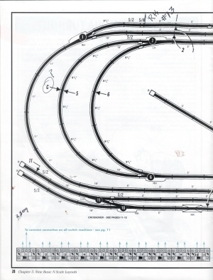
I disconnected one of the tracks going to the turnout I'm having trouble with, it works now. Si I'll have to use some of investigative skills I learned at my last job, scratch my head and see what happens. I am going to follow you suggestion and remove the plastic joiners and make sure all of the joints are tight. Wish me luck. The turnouts just click when used as directed. :) I really enjoy the plethora of information here. THANKS!


Ha! Well all the engineers on my railroad are highly experienced and safety minded. So I don't need that. (just kidding). It does remind me, I was using "Engine Driver" on my phone, when the connection dropped there was no dead man switch! So the loco just kept going!!! Yikes!!!


Affiliate Disclosure: We may receive a commision from some of the links and ads shown on this website (Learn More Here)

Back
Top
