New Layout

ModelRailroadForums.com is a free Model Railroad Discussion Forum and photo gallery. We cover all scales and sizes of model railroads. Online since 2002, it's one of the oldest and largest model railroad forums on the web. Whether you're a master model railroader or just getting started, you'll find something of interest here.


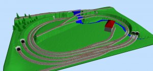
Okay, how about this one? I have a runaround/siding now. Also put in some bridges, maybe put a river back there with a waterfall over the outmost track? What does everyone think?
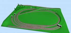
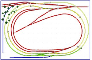
phase 1 r6 3D.jpgphase 1 r6.jpg
 
Getting more interesting! No sidings inside the loop? I'd extend the mountainside up further(higher off the table) on both sides, and add a mountainous backdrop.
 
I thought about a siding inside the loop. I do have a model of a brewery that matches the time period I'm going for (1930s - ironically, prohibition). I want to try and capture the corruption of that time period, so a brewery with a rail car being loaded up by men with tommy guns. I just think that would be an awesome scene.

Dammit... now I have to put in a siding inside the loop. I was trying to save a lot of space for an opening so I can get in there (my arms are not that long). I thought about the mountain backdrop, but the layout is accessible from three sides, bottom, right, and top in the pictures. With all of the scenery and models that will be in the center, I need to be able to get in there, even if it is a drop-in section. Back to the drawing board...


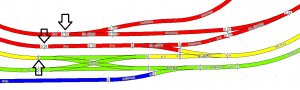
So, I added the siding, and it made me realize the different elevations of track within close proximity. Its not much elevation change, but its something. Is there any guideline as to how far the tracks should be from each other when in this situation? For instance, two parallel tracks are 2" apart. If there is a 1/2" difference in elevation between the two parallel tracks, would it change to 2.5" or 3" apart?
elevation pitch question.jpg
 
Just a quick reassurance, if you are going for the 30s, don't worry about prohibition. That ended in 1932. So just go for 1933 or later and you're fine. :D

From the DairyStatePhone
 
Depending on the feedback about the track pitch at elevation changes, I think my track planning is complete. I put a structure that is roughly the size of the brewery to see how much space it would take. I'm thinking a road that goes from the coal mine straight to the brewery tap room is in order also...

phase 1 r6 w terrain 3D.jpg
 
So, I added the siding, and it made me realize the different elevations of track within close proximity. Its not much elevation change, but its something. Is there any guideline as to how far the tracks should be from each other when in this situation? For instance, two parallel tracks are 2" apart. If there is a 1/2" difference in elevation between the two parallel tracks, would it change to 2.5" or 3" apart?
Not necessarily, just make certain the train on the lower track won't rub the edge of the sub-roadbed/roadbed of the upper track. Roadbed can be very narrow if you need it to be.
 
Okay, so I realized that I had not posted about the layout progress since late January. Now that it is May, I suppose I can post an update. As mentioned earlier in this thread, my layout is a long term project, as life typically gets in the way of fun stuff - like building a model railroad - so it may seem to some that the progress is very little. Considering how much time I've actually spent on it, I think its pretty good.

In the post I made here, the plans were just coming together. I haven't done any more work in SCARM, so the design looks the same, but the image in my head continues to mature. You can get some idea from the pictures.

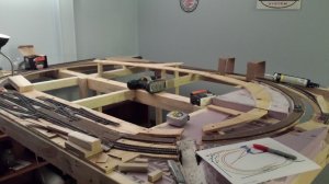
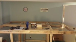
First picture is after I had the outside loop. It is a good picture to show the space being used.
20131124_211459.jpg
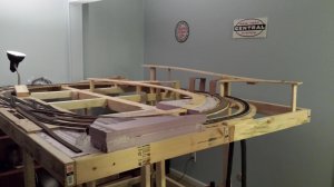
Here it is last night. Almost all of the wood is in. I started adding the ping foam in areas that will be built up simply, and also to start working on the river and pond. The river will flow next to the brewery, as to imply that the brewery gets it's water naturally (not Coors though, I'm not a big fan). The coal line is pretty much defined also. I didn't put the surface in for the mine itself yet, as I'm waiting to design and build the mine. Once that is done, I'll be able to properly plan the amount of space needed. Speaking of coal mines, I want to put loads in my coal hoppers so I asked some friends where I could get a hand full of actual coal. One friend has grandparents that used to own a coal mine in Zanesville, Ohio. The mine is now closed but the structures and mine are all still there. We plan to take a trip out in July to visit and take pictures so that I can model after a true mine. AND, I'll bring back some coal for my layout!
20140427_211953.jpg
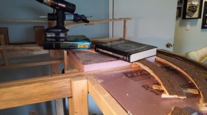
Here, Just a picture to show how I put the foam in. Not a very good way of doing things, as now I will have to notch out the wood frame where the river will flow through. Poor planning on my part. The old textbooks and drill are holding down the cork roadbed until the caulk dries underneath. The tighter radii curves certainly take longer to really set up.
20140502_182556.jpg
 

Attachments

  • 20140425_205350.jpg
    20140425_205350.jpg
    118.6 KB · Views: 470
I now see that a picture I tried deleting shows up as an "attached thumbnail". I tried deleting because it was a picture of in-between progress, so now you get a look at that. You can see by the mess that work is on-going.

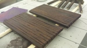
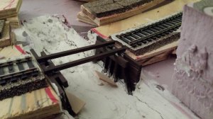
In that attached picture, you can see where the river is started at the bottom of the picture. For that outside line, I built a small bridge. Real simple design - I used the "wing it" approach. With the small span, I didn't plan to put any support in the middle. I know, not very prototypical but I'm not a rivet counter, so its okay. I took two solid pieces of Bass wood and scribed them to look like boards that are stacked. Then built the supports that would be mounted to them (you can see one in the top of the first picture).

20140412_234945.jpg
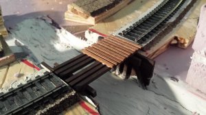
I cut out the foam for the river, then put drywall compound (had some left over) for the roadbed. While the compound was still wet, I placed the walls and supports in. I lined them up as close as I could for height. After the compound dried (I went back a couple of days later, may have been dry for a while), I glued down the stringers, one that runs under each rail. I let those dry overnight and returned to add the remaining four stringers.
20140427_213356.jpg
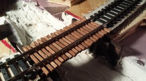
After the glue dried on the remaining stringers, I glued down the ties. On a previous [much longer] bridge, I used spacers to ensure the look of the bridge. This one I wanted to look a little more "cheap" as to imply the mainline is not very well taken care of. So, I laid the ties by hand with no spacers, only the eyeball. I actually really like the way they look in the end.
20140502_182533.jpg
I put the rails on, joined them up, soldered and spiked. This short span, if a locomotive is so heavy, it is longer than the bridge itself! I'm happy with how it came out. Should also look a lot better after the surrounding scenery is put in.
20140502_204923.jpg
 
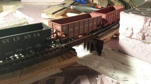
And a bonus picture. Just to put the whole thing to scale.

Still have to get to weathering the piece also. Anyone have any suggestion on if I should wait until the scene is complete, or weather now, and build the scene around it?
20140502_211950.jpg
20140502_220517.jpg


Looks like you guys are doing great. Keep the updates coming, I am very interested in the progress as my layout is the same size as yours.

Thanks
Scott
 
Ah yes, that "cork on plywood" stage of the layout, my favorite! (must be the smell)
This is coming along very nicely!
 
This is not a critique bklynman, of what you've done here, but in the future when you build another bridge, don't end the track for the bridge, right at the ends of the bridge. To insure a smooth transition from the bridge rail to the "land" rail, extend the bridge track ends at least 2", (if HO, 1" if N) past the ends of the bridge. It's not good practice to have rail ending over a joint in the roadbed & subroadbed, like in a module's edge or bridge end. Sometimes it can't be helped, as when there is a turnout at the very end of a bridge, and unless you handlay your track, a joint in the subroadbed, roadbed and then the track is unavoidable in this situation.

The difference in elevation, angle, grade, is always exaggerated at the rails, as they are at the very top of this difference. The difference can be so slight, as to be almost invisible, except in a photograph, as yours is in the second photo. Have you ever seen a modular layout that had the rails end at the module's edge, and the trains seem to almost "ski jump" when going across a modular joint? That is what you can get when the rails end directly at the ends of a bridge. Couple of ways to handle it is you can have the rails on the adjoining pieces of track cut back that 2" and leave the ties and spike heads for the bridge rails to slide into, or have short pieces of the tie strip slid onto the 2" of extra bridge rail. These methods also helps locate and secure the bridge in place.

Please don't take this the wrong way, the bridge actually looks great, I know that you're very pleased and proud, as you should be. But from the picture you can tell the rail doesn't look quite as smooth as it should. A longer piece of rail that goes past both bridge ends would make it a smoother transition up to and across the bridge, without the danger of looking like a "ski jump".
 
Last edited by a moderator:
This is not a critique bklynman, of what you've done here

CJ, there are two reasons I post on the forum - 1)To gloat about what I've done, and 2) to learn better ways to do those things. Not only do I not take your comments critically, but I appreciate your telling me these things. Otherwise, I would go on building this stuff the wrong way and never understanding why it doesn't work as well as the pros' stuff!

You are correct, there is the problem with the bridge where one side is a touch higher than the track outside of it. You can barely see in the picture with only the coal cars that the joining track has a small shim under it. This was done to bring the level of the track up to the bridge before the rail joints. I did spend some time with those cars rolling them back and forth until it felt smooth enough for me to be comfortable with. Those cars were chosen specifically because they all have metal wheels, and I find it easier to hear problems as well as see them. I contemplated filing down the rail on the bridge until they met up properly, but was worried about bringing it down too far. I am using code 100, so there shouldn't be too much trouble, but decided against it anyway. As you can see, there will be two additional bridges built along side of this one. I'll be sure to do things a bit differently for those (like having the rail extend beyond the bridge). Thank you for the input!

I do have a question - what I did was use a piece of track, removed the rails from the ties and cut to size, then installed the rails to the ties. Would it be better to use that entire piece of flex track and only cut out the ties from the bridge section? What I mean is, instead of only going past the bridge ends by 2", use the entire 3' section with the bridge in the middle. Or would this look strange since the bridge rails would be expected to end just off the bridge?

Obviously, this layout is a learning curve. I'm happy to belong to a forum that helps this curve be a bit smaller than it needs to be!
 
I just thought of, the guide rails (inside the running rails) are not installed yet. I can run these out past the edge of the bridge to help prevent derailments when going over the small hump spot. You think that would help, or would it look strange?
 
Guard rails definitely help out, both in appearance and function. I would install them. As to using a full piece of flex track, while it is up to you, I wouldn't. For one reason if you ever have to dismantle the layout, a 3' piece of flex with something dangling underneath makes it harder to store until it's ready to be used again. Reason two. If you've thought just unspiking the bridge from that rail, it will leave holes that the next time it's assembled, won't hold the track well, and if the bridge flexes the spikes could work their way out some. You can make that 2" of overhang longer if you want, that is just a convenient length that I have used, it's nothing carved in stone.

One thing that you could do now to improve the bridge is to extend that shim underneath the regular track to make the approach to the bridge longer so the track could/would be more level and it would help lessen the "hump".

What you done so far looks real good, and in regards to the construction of the bridge it self, seems to be a technique that works well for you. Keep up the good work!
 
Last edited by a moderator:


CJ, I did put some guide rails in, but don't have any pictures of it yet. I'll get some tonight when I'm home to share.

I was watching this video on YouTube about ballasting and thought it seemed like a good method. I want to ask, does anyone disagree? If so, what would be a better method?
[video=youtube_share;Vr_2EdbCRFU]http://youtu.be/Vr_2EdbCRFU[/video]

Thanks for the input!


Affiliate Disclosure: We may receive a commision from some of the links and ads shown on this website (Learn More Here)

Back
Top