New Layout - Switching Scales - Topeka ATSF 1970-71

ModelRailroadForums.com is a free Model Railroad Discussion Forum and photo gallery. We cover all scales and sizes of model railroads. Online since 2002, it's one of the oldest and largest model railroad forums on the web. Whether you're a master model railroader or just getting started, you'll find something of interest here.


That is a very interesting plan Jacob. At least it does give you an idea of what you can do. Over the years I have seen a number of posts for layouts and I think every one of them got a little bit of tweaking along the way to construction. I never had a drawn out track plan, but like you, I did know what I wanted and even though I may have gone about it the wrong way, by just starting to lay track and then work my different rail customers into the space available, it did work out.

I built a freelance railroad, but with your knowledge of the railroad and the area you're interest in, you shouldn't have a problem. I'm really looking forward to see what you come up with.
 
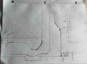
It's an L shape. I've attached a diagram. It's roughly 450 square feet. I've built my workbench and tool area in area under stairs.
So If the tool box is under the stairs, the landing is at the top of the diagram and that door on the upper right is the main entrance to the room?

A minimum radius was not mentioned. Considering passenger cars, 30' or 32' should probably be the minimum.
 
Yea - right now I have entrances in upper right (Southeast) and lower right (Southwest) of drawing. Neither is framed with doors yet. My old O layout traveled through these areas - but I've promised my wife a separate non-train basement space - so I cannot expand outside the L.

The landing is at the top of the diagram (Southeast).

I was assuming 30" minimum.


I was afraid that toolbox might be too high, had it been 4', it could have been placed under the layout. I'm in agreement with Iron Horseman re radius's for passenger cars and the minimum I used on that plan are 30". So, you need the access through the hallway which I've left open at the moment. Placing that toolbox down into the corner of that 2' x 15' area would then also mean allowing space for frontal access to it. Will see if the t/box can be juggled around on an angle so the passageway can do double service for access to it. I was looking at modifying the loop in that area (smaller radius from it's as drawn 36") to possibly allow extending the length of the wye trackage. I'll also look at altering the plan at the top (southeast corner) to see if the t/box can be accommodated back there. A sliding door to access the layout via the stairway would be a better option as well to eliminate the door itself intruding into the layout room.

Will do another "rendition" tonight. (early hours your time)
 
Another thought, you show that southwest hall as being 5' wide, could that t/box actually be placed in there against the lower wall? If it's less than 2' deep, would still allow 3' of walking space past it.
 
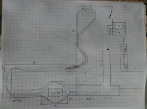
I'm playing with something along these lines... IMG_20160426_193601.jpg
 
Is that inverted T at the lower right intended for railroad tracks, or is it a workbench? Can't quite make out what's written beside it. Infill the corners at the left end with triangles to ease the curves around them.
 
Also run a siding along the wall from the top of the loop to the southeast corner, room for an industry there. Consider a wall-face mounted sliding door that slides behind the T/box (i.e. move the box out from the wall to clear it, there's enough room to do that) rather than the hinged one to eliminate it needing floor space to open into.
 
Is that inverted T at the lower right intended for railroad tracks, or is it a workbench? Can't quite make out what's written beside it. Infill the corners at the left end with triangles to ease the curves around them.

Exploring that as a yard. As mentioned earlier in the thread - Topeka's main yard where the railroad shops are is a T shape - the main yard and shops parallel Adams Ave. while the Industries are mostly along 1st St (and later Seward to the east). At 10th there is a wye for the yard and industries. So I was thinking I could utilize that design and take the tracks from there as though they are headed south to Pauline.
 
Last edited by a moderator:


The tweaking has begun. It sure helps when you have as much knowledge as you of the area Jacob. Really enjoy watching a plan come together.
 
As mentioned earlier in the thread - Topeka's main yard where the railroad shops are is a T shape - the main yard and shops parallel Adams Ave. while the Industries are mostly along 1st St (and later Seward to the east). At 10th there is a wye for the yard and industries. So I was thinking I could utilize that design and take the tracks from there as though they are headed south to Pauline.
I am fascinated by the crossing of the passenger station lead over the track that crosses the river. I've been trying to work that in. Seems like that is the ubiquitous piece of track from the 1885 map through to the current day that says "this is Topeka".

I'm having a hard time finding reference material. Seems it is all really old, or current. Nothing from the 1960-1970 period. On the current line from Emporia for industries there is only the stuff in Pauline, one siding for a COOP in Carbondale, and the work tracks and passing siding north of Osage, while I assume in the 1970s there were at least industrial sidings in Wakarusa, Carbondale, Scranton, Burlingame, Osage, Barclay, and Reading. Even maybe an interchange in Osage where they crossed the Mopac.
 
Haven't been following this thread to closely. Have you looked at the track charts from the Santa Fe Railway Historical & Modeling Society? (http://www.atsfrr.com/links/atsf/track.htm) You have to be a member but the track charts & all the other info available thru the site is the best!

Funny you mention the society. When I was at Emporia State University, I performed all the digitization, conducted all the research, and created all the metadata for the Walter M. Anderson Collection (it's actually spelled Andersen) which is at the Emporia State University Archives. The Modeling Society use a ton of those photos on their website.
 
Last edited by a moderator:
I am fascinated by the crossing of the passenger station lead over the track that crosses the river. I've been trying to work that in. Seems like that is the ubiquitous piece of track from the 1885 map through to the current day that says "this is Topeka".

I'm having a hard time finding reference material. Seems it is all really old, or current. Nothing from the 1960-1970 period. On the current line from Emporia for industries there is only the stuff in Pauline, one siding for a COOP in Carbondale, and the work tracks and passing siding north of Osage, while I assume in the 1970s there were at least industrial sidings in Wakarusa, Carbondale, Scranton, Burlingame, Osage, Barclay, and Reading. Even maybe an interchange in Osage where they crossed the Mopac.

As much as a lift-out duck-under are not my desire, I'm playing with the idea of looping the track in a 25' x 9' oval layout with an 18' operating section extending into the other part of the room. A short industry track could then be added at the very top towards the door. This would allow the passenger track to cross the freight track as it does in Topeka. Thinking a Wye might be built in the 7' x 2' Alcove.
 
See if you can find any Santa Fe CLICs for your area. These came out when Santa Fe computerized everything in the '80s. But most of the industries from your era should be included if they were still active in the '80s.
 
Playing around with some alternative benchwork arrangements. My time has been limited. Hoping to get back to in the next few weeks and start building benchwork.

Anyways, here's a dogbone benchwork plan I'm playing around with that eliminates both duck-unders and long reaches.IMG_20160510_211126.jpg
 
Playing around with some alternative benchwork arrangements. My time has been limited.
Hmmm, me to. I was thinking about three different arrangements. One just didn't work at all. But the other two have potential. instead of trying to explain I'll have to scan and upload. One has a really long run, but is complex.


Hmmm, me to. I was thinking about three different arrangements. One just didn't work at all. But the other two have potential. instead of trying to explain I'll have to scan and upload. One has a really long run, but is complex.

Excellent! I look forward to seeing what you come up with. I've really been struggling with scaling down and deciding how best to utilize the space.


Affiliate Disclosure: We may receive a commision from some of the links and ads shown on this website (Learn More Here)

Back
Top