I use PECO insulfrog turnouts on my DCC layout. I set up a small track testbed with a simple loop and one siding. Put a loco on the loop track, and another on the siding. With the turnout set so the loop was complete, the loco there ran, but the one on the turnout did not get any power. So I added power to the siding by adding feeder wires, and everything worked fine -- I could run the loco on the loop and the loco on the siding at the same time. The problem is on my full layout. It's basically the same . . . a very large loop with lots of sidings. But when I wired both the main track and the sidings for power, I got a short. Nothing runs. Theoretically, the large layout is the same as the testbed, but the results are different. Anyone have a solution for my main layout? Thanks in advance for any advice.

You are using an out of date browser. It may not display this or other websites correctly.
You should upgrade or use an alternative browser.
You should upgrade or use an alternative browser.
Need help with wiring problem
- Thread starter Taggart
- Start date
ModelRailroadForums.com is a free Model Railroad Discussion Forum and photo gallery. We cover all scales and sizes of model railroads. Online since 2002, it's one of the oldest and largest model railroad forums on the web. Whether you're a master model railroader or just getting started, you'll find something of interest here.


I've attached a diagram of the problem. I tried feeding power at A, B, and C, but got shorts. Same at E and D. Locos run perfectly on the main loop if I don't feed the turnouts. So what do I need to do so I can run switchers on the turnouts?


That's just not accurate. I have a number of such sidings, and it does NOT require that both be set to the same route. Yes, insulfrogs do PROVIDE power across the frog, but they don't ROUTE the power. The power is jumped across the dead frog to the appropriate rail, which remains the same no matter which direction the turnout is thrown. As long as your rails are properly wired it doesn't make any difference. Rail A comes back to rail A. Same with rail B. You can have the turnouts in any position you wish and they will work. The only time you MUST gap rails when using insulfrogs is when you have a reversing loop.
Unless you're confusing which rail is which, there shouldn't be any issue with insulfrogs. This may seem like a silly question, but are you sure you don't have electrofrogs in there? If you've traced the rails and don't have your drops wired backward, there shouldn't be any reason those won't work.
I bought some used Peco turnouts a few years ago when I was just getting back into the hobby and the guy said the were insulfrog. I hadn't been in the hobby since the 70's, was still a little shaky on what was what, and I didn't really pay attention. Wired an electrofrog in without realizing it WAS an electrofrog and of course my entire layout was shorted. I'd never make the same mistake now, but as a newbie I just wasn't paying enough attention and didn't have the experience to immediately spot the difference.
EDIT: Here's a diagram that will hopefully show you more exactly what's going on and how it needs to be wired. Again, assuming you do have insulfrogs and are not planning on more advanced features such as signaling and block detection.
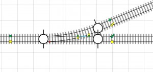
The left green and yellow blocks will be your drops to the main. With no further drops, here's what happens: First, the power from green block to green block will be there regardless, as will the power from yellow block to yellow block. They're connected by a solid length of rail. The blue funky shape is your insulated frog. It has jumper wires connecting the two yellow dots together and the two green dots together. They pass each other without touching inside the turnout. So as shown in this pic, yellow block power SHOULD be getting to the yellow checkmark via that jumper between the yellow circles and the point where the turnout point is touching the yellow rail. The problem is that the point of connection (red dot) with only that one wire drop can be rather tenuous. Things such as corrosion and/or dirt can keep it from making good contact and it can become a dead point instead of a point of contact. Your best practice would be to put an additional wire drop at the yellow checkmark. Then there's the fact that if you throw the turnout to the opposite position there would no longer be ANY contact, however tenuous, going to the yellow checkmark, and it would just be dead rail at that point.
The green checkmark, of course, would be getting no power at all with the turnout in this position. If you want to run trains on that track at all, just like above, while the turnout is in this position, then you MUST have an additional wire drop at the green checkmark. Otherwise that track will just be dead until the turnout is thrown to the other position.
Obviously you'd have more wire drops further down the line on the main, but this really illustrates why you must have wire drops on the diverging frog rails on a siding in order for those rails to be powered if the turnout is in the "wrong" position.

On the other hand reversing sections in the layout design require gaps regardless of turnout type. Unfortunately, for some reason I am unable to open your pdf, so I cannot help further diagnose the problem.
Also agree with the question- are you certain you didn't get an electrofrog turnout in there somewhere by mistake?
The PDF doesn't show the whole layout, only a section of it. I'm going with the assumption that the rest of it is just a circle, oval, ovoid type thing that doesn't reverse onto itself. It seems that the turnouts are the problem providing my assumption is correct. And yes, I'm aware of what an ass I am for assuming
http://www.dccwiki.com/Wiring_Turnouts
I don't think you understand the terms used in the wiki you posted. Peco insulfrogs are self-ISOLATING, not self-ROUTING. The Wiki is misleading. Well, not so much misleading as it just doesn't really talk about insulfrogs. Except for a couple of sentences, everything in there is about wiring electrofrogs, because insulfrogs just don't need much info. Hook them up. Run trains.
But because they are self-isolating and not self-routing, Peco insulfrogs do not ever short out just because their spur rejoins the same line further down the line. There would have to be a reversing loop in order for there to be a need to isolate the diverging frogs of a Peco insulfrog.
I think you're getting some of your information confused between the two types, and that wiki is far from clear as to which is which. The entire Wiki is basically addressing electrofrog, with only a glancing reference to insulfrog and no information about them. The previous reply I posted with its graphic is far more illuminating.
It's possible that whatever problem you thought existed with insulfrogs in the past that you thought was eliminated by rail gaps or having both turnouts set to the same route was the result of a wiring mistake that was remedied by accident. There is no basis for both turnouts needing to be thrown to the same route with insulfrog regardless. It's only with electrofrog that one needs to worry if they're gapped. I have quite a few sidings to prove that point.
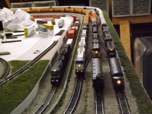
Not a gapped rail in sight:
Whoops, I lied. There is a gap you can see in the local line still under construction to the left. The figure eight has since been completed and that little section of track is part of a reversing "loop" between the two lobes of the figure eight. Everything pictured on the mainline, though, is completely gapless and completely functional regardless of turnout position.
The frog is visually different. The point of the frog on a Insulfrog turnout is plastic, on a Electrofrog it is metal.
At least it is on mine.
Yes, power is passed from the fixed divergent rails to the points. Always. But again, an insulfrog is self-ISOLATING, not self-ROUTING. The routing of the power never changes in an insulfrog. Power routing usually indicates a live frog or frog rails that need to be isolated due to the polarity change that occurs when points are switched from one rail to the other. The frog is live and attached to both diverging rails and thus power routing changes as the turnout is thrown from one rail to the other. This never occurs in an insulfrog because the divergent rails and the points are insulated from each other. No matter which way the turnout is thrown, it can't short out even with constant power applied on the diverging ends and with no gaps. Regardless of what you think you're reading, there is never any need (barring block detection and signaling) to gap or insulate the rails as they diverge from an insulfrog turnout unless you're dealing with a reversing section. You keep claiming that a siding which diverges and then reconnects, still going in the same direction with no loop-back, will short out. This is simply and inarguably not true. I can take another half-dozen pictures of my perfectly functioning layout, or even video if you prefer, which illustrate that what I'm saying is absolutely true. If you're not dealing with a reversing section, you never ever have to gap the diverging rails on an insulfrog turnout strictly for power purposes.
EDIT: My post below made me realize that I was assuming N-scale, which is all I'm really familiar with. It's my understanding that the HO turnouts work exactly the same, but if that's wrong for some reason, then maybe a third party could clear this up. I do know for a fact that Peco's instructions do not in any way apply to N-scale insulfrogs, and I really doubt that HO is any different but I could be wrong. I would imagine that blanket statement that ALL turnouts need to be insulated is more to save them headaches and questions if they tried to explain the differences and people got confused about which was which.
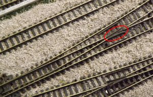
EDIT: I'm just getting myself confused here. For some reason I thought I was in the N-scale section instead of the wiring section. SO. I'll include both N-scale and HO. First, here's an N-scale turnout. The black area circled in red is the insulating plastic you'll see in an insulfrog turnout. If it's an electrofrog, that black area would instead be the same metal as the rails.
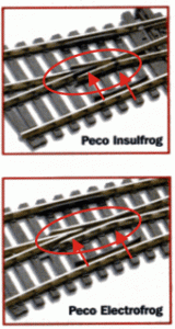
This is an HO turnout. The arrows point to the places where the plastic insulators would be on an insulfrog and where they are NOT on an electrofrog. The electrofrog rail is just all metal with no plastic insulators at that point.

Affiliate Disclosure: We may receive a commision from some of the links and ads shown on this website (Learn More Here)
jdetray
Well-Known Member
It can be difficult to troubleshoot after everything has been wired.
I would disconnect the wiring to the sidings one at a time until the short disappears. Then start reconnecting the sidings one at a time but test the layout after each siding has been connected. Connect a siding and test. Connect another siding and test, etc.
If a short develops at any point, do not connect any further wiring until you find the cause of the short. The most common cause of a short is unintentionally swapping the left and right feeders.
Good luck.
- Jeff
I would disconnect the wiring to the sidings one at a time until the short disappears. Then start reconnecting the sidings one at a time but test the layout after each siding has been connected. Connect a siding and test. Connect another siding and test, etc.
If a short develops at any point, do not connect any further wiring until you find the cause of the short. The most common cause of a short is unintentionally swapping the left and right feeders.
Good luck.
- Jeff
Genetk44
Active Member
The most common reason for Insulfrog shorts appears to be a wheell contacting both rails across the plastic frog...here are a few links about the problem and various fixes.
http://railwaybobsmodulebuildingtips.blogspot.ca/2011/06/fixing-short-in-peco-insulfrog.html
http://www.wiringfordcc.com/switches_peco.htm
http://railwaybobsmodulebuildingtips.blogspot.ca/2011/06/fixing-short-in-peco-insulfrog.html
http://www.wiringfordcc.com/switches_peco.htm
Last edited by a moderator:
trailrider
Well-Known Member
That could, indeed be the trouble. You should also check to be sure you are feeding the turnouts from the point end, and you may need a gap or insulated rail joiners on the frog end of a turnout in case you inadvertantly have a feedback around the loop.
josephbw
Active Member
If I'm reading it right you have a short because you need to have a reversing section somewhere in the loop. Trace your rails around the loop. Label one side A the other B. When you get to the switch you will see that A & B are now on the same rail causing a short. 1st isolate the loop with insulating rail joiners, then wire up a DPDT switch so that you reverse the current on both rails in the isolated area. If you are running DCC this will also work or you can install an automatic reversing module that will do the same thing electronically.
Joe
Joe
If I'm reading it right you have a short because you need to have a reversing section somewhere in the loop. Trace your rails around the loop. Label one side A the other B. When you get to the switch you will see that A & B are now on the same rail causing a short. 1st isolate the loop with insulating rail joiners, then wire up a DPDT switch so that you reverse the current on both rails in the isolated area. If you are running DCC this will also work or you can install an automatic reversing module that will do the same thing electronically.
Joe
I've attached a diagram of the problem. I tried feeding power at A, B, and C, but got shorts. Same at E and D. Locos run perfectly on the main loop if I don't feed the turnouts. So what do I need to do so I can run switchers on the turnouts?
Attachments
Selector
Well-Known Member
IMPORTANT!! Peco insulfrog turnouts are "power routing." That means the points rails contact the through rails and the closure rails....for the through route and the diverging route, and get power along them that way. Therefore, when you have a turnout routed the wrong way for the other side of the siding IF it is fed by another insulfrog turnout, you'll get the confounded polarity problem...or phase problem in DCC.
If your siding is open-ended...no turnout allowing through traffic to rejoin the main, only a bumper or dirt/log pile to stop runaways, then it doesn't matter which way your points rails are set. But, if you have a double-ended siding with a power-routing turnout on each end, you must have both turnouts lined for only one of the routes at the same time. However...
You can gap one of those two turnouts right where its rails end, both routes. Just leave a 1/16" gap there, no joiner, and you can join the other turnout as one would normally do. Run a pair of feeders to the rails that match the polarity of the joined turnout at the one end. The gapped turnout will supply power to its own rails up until the gap. The gap will avoid a short.
If your siding is open-ended...no turnout allowing through traffic to rejoin the main, only a bumper or dirt/log pile to stop runaways, then it doesn't matter which way your points rails are set. But, if you have a double-ended siding with a power-routing turnout on each end, you must have both turnouts lined for only one of the routes at the same time. However...
You can gap one of those two turnouts right where its rails end, both routes. Just leave a 1/16" gap there, no joiner, and you can join the other turnout as one would normally do. Run a pair of feeders to the rails that match the polarity of the joined turnout at the one end. The gapped turnout will supply power to its own rails up until the gap. The gap will avoid a short.
MikeOwnby
Active Member
IMPORTANT!! Peco insulfrog turnouts are "power routing." That means the points rails contact the through rails and the closure rails....for the through route and the diverging route, and get power along them that way. Therefore, when you have a turnout routed the wrong way for the other side of the siding IF it is fed by another insulfrog turnout, you'll get the confounded polarity problem...or phase problem in DCC.
If your siding is open-ended...no turnout allowing through traffic to rejoin the main, only a bumper or dirt/log pile to stop runaways, then it doesn't matter which way your points rails are set. But, if you have a double-ended siding with a power-routing turnout on each end, you must have both turnouts lined for only one of the routes at the same time. However...
You can gap one of those two turnouts right where its rails end, both routes. Just leave a 1/16" gap there, no joiner, and you can join the other turnout as one would normally do. Run a pair of feeders to the rails that match the polarity of the joined turnout at the one end. The gapped turnout will supply power to its own rails up until the gap. The gap will avoid a short.
That's just not accurate. I have a number of such sidings, and it does NOT require that both be set to the same route. Yes, insulfrogs do PROVIDE power across the frog, but they don't ROUTE the power. The power is jumped across the dead frog to the appropriate rail, which remains the same no matter which direction the turnout is thrown. As long as your rails are properly wired it doesn't make any difference. Rail A comes back to rail A. Same with rail B. You can have the turnouts in any position you wish and they will work. The only time you MUST gap rails when using insulfrogs is when you have a reversing loop.
Last edited by a moderator:
MikeOwnby
Active Member
I've attached a diagram of the problem. I tried feeding power at A, B, and C, but got shorts. Same at E and D. Locos run perfectly on the main loop if I don't feed the turnouts. So what do I need to do so I can run switchers on the turnouts?
Unless you're confusing which rail is which, there shouldn't be any issue with insulfrogs. This may seem like a silly question, but are you sure you don't have electrofrogs in there? If you've traced the rails and don't have your drops wired backward, there shouldn't be any reason those won't work.
I bought some used Peco turnouts a few years ago when I was just getting back into the hobby and the guy said the were insulfrog. I hadn't been in the hobby since the 70's, was still a little shaky on what was what, and I didn't really pay attention. Wired an electrofrog in without realizing it WAS an electrofrog and of course my entire layout was shorted. I'd never make the same mistake now, but as a newbie I just wasn't paying enough attention and didn't have the experience to immediately spot the difference.
EDIT: Here's a diagram that will hopefully show you more exactly what's going on and how it needs to be wired. Again, assuming you do have insulfrogs and are not planning on more advanced features such as signaling and block detection.
The left green and yellow blocks will be your drops to the main. With no further drops, here's what happens: First, the power from green block to green block will be there regardless, as will the power from yellow block to yellow block. They're connected by a solid length of rail. The blue funky shape is your insulated frog. It has jumper wires connecting the two yellow dots together and the two green dots together. They pass each other without touching inside the turnout. So as shown in this pic, yellow block power SHOULD be getting to the yellow checkmark via that jumper between the yellow circles and the point where the turnout point is touching the yellow rail. The problem is that the point of connection (red dot) with only that one wire drop can be rather tenuous. Things such as corrosion and/or dirt can keep it from making good contact and it can become a dead point instead of a point of contact. Your best practice would be to put an additional wire drop at the yellow checkmark. Then there's the fact that if you throw the turnout to the opposite position there would no longer be ANY contact, however tenuous, going to the yellow checkmark, and it would just be dead rail at that point.
The green checkmark, of course, would be getting no power at all with the turnout in this position. If you want to run trains on that track at all, just like above, while the turnout is in this position, then you MUST have an additional wire drop at the green checkmark. Otherwise that track will just be dead until the turnout is thrown to the other position.
Obviously you'd have more wire drops further down the line on the main, but this really illustrates why you must have wire drops on the diverging frog rails on a siding in order for those rails to be powered if the turnout is in the "wrong" position.
Last edited by a moderator:
Iron Horseman
Well-Known Member
Agree, the behavior being described by Selector is that of the Peco Electrofrog (or any hot frog type turnout for that matter - e.g. Shinohara). Insulfrogs are just like Altas and do not require any gaps in and of themselves.That's just not accurate.
On the other hand reversing sections in the layout design require gaps regardless of turnout type. Unfortunately, for some reason I am unable to open your pdf, so I cannot help further diagnose the problem.
Also agree with the question- are you certain you didn't get an electrofrog turnout in there somewhere by mistake?
Last edited by a moderator:
MikeOwnby
Active Member
Agree, the behavior being described by Selector is that of the Peco Electrofrog (or any hot frog type turnout for that matter - e.g. Shinohara). Insulfrogs are just like Altas and do not require any gaps in and of themselves.
On the other hand reversing sections in the layout design require gaps regardless of turnout type. Unfortunately, for some reason I am unable to open your pdf, so I cannot help further diagnose the problem.
Also agree with the question- are you certain you didn't get an electrofrog turnout in there somewhere by mistake?
The PDF doesn't show the whole layout, only a section of it. I'm going with the assumption that the rest of it is just a circle, oval, ovoid type thing that doesn't reverse onto itself. It seems that the turnouts are the problem providing my assumption is correct. And yes, I'm aware of what an ass I am for assuming
Selector
Well-Known Member
That's just not accurate. I have a number of such sidings, and it does NOT require that both be set to the same route. Yes, insulfrogs do PROVIDE power across the frog, but they don't ROUTE the power. The power is jumped across the dead frog to the appropriate rail, which remains the same no matter which direction the turnout is thrown. As long as your rails are properly wired it doesn't make any difference. Rail A comes back to rail A. Same with rail B. You can have the turnouts in any position you wish and they will work. The only time you MUST gap rails when using insulfrogs is when you have a reversing loop.
http://www.dccwiki.com/Wiring_Turnouts
MikeOwnby
Active Member
I don't think you understand the terms used in the wiki you posted. Peco insulfrogs are self-ISOLATING, not self-ROUTING. The Wiki is misleading. Well, not so much misleading as it just doesn't really talk about insulfrogs. Except for a couple of sentences, everything in there is about wiring electrofrogs, because insulfrogs just don't need much info. Hook them up. Run trains.
But because they are self-isolating and not self-routing, Peco insulfrogs do not ever short out just because their spur rejoins the same line further down the line. There would have to be a reversing loop in order for there to be a need to isolate the diverging frogs of a Peco insulfrog.
I think you're getting some of your information confused between the two types, and that wiki is far from clear as to which is which. The entire Wiki is basically addressing electrofrog, with only a glancing reference to insulfrog and no information about them. The previous reply I posted with its graphic is far more illuminating.
It's possible that whatever problem you thought existed with insulfrogs in the past that you thought was eliminated by rail gaps or having both turnouts set to the same route was the result of a wiring mistake that was remedied by accident. There is no basis for both turnouts needing to be thrown to the same route with insulfrog regardless. It's only with electrofrog that one needs to worry if they're gapped. I have quite a few sidings to prove that point.
Not a gapped rail in sight:
Whoops, I lied. There is a gap you can see in the local line still under construction to the left. The figure eight has since been completed and that little section of track is part of a reversing "loop" between the two lobes of the figure eight. Everything pictured on the mainline, though, is completely gapless and completely functional regardless of turnout position.
Last edited by a moderator:
Follow-up question
Mike . . . many thanks . . . that was the best explanation and most help I've ever had on this problem . . . I seem to have one of two problems: (1) either an electrofrog has snuck into the layout, or (2) I've got my feeder wires to the turnouts backwards. The latter is easy enough to check. But with the turnouts glued down, and a continuity meter in hand, what's the simple test to see whether any given turnout is insul- or electro- frog? --Gary
Mike . . . many thanks . . . that was the best explanation and most help I've ever had on this problem . . . I seem to have one of two problems: (1) either an electrofrog has snuck into the layout, or (2) I've got my feeder wires to the turnouts backwards. The latter is easy enough to check. But with the turnouts glued down, and a continuity meter in hand, what's the simple test to see whether any given turnout is insul- or electro- frog? --Gary
Mike ... that was the most helpful response I've had ... made things very clear. So either I have an electrofrog that's somehow slipped into the picture or else I have the feeder wires reversed. The latter is easy to check. For the former, since the turnouts are glued down, if I use a continuity meter what's the simple test for determining whether a given turnout is electro- or insul- frog?
Selector
Well-Known Member
Mike, I have metered my large stable of Peco Insulfrog Streamline Code 83 turnouts quite a few times to see if they are routing power, which they most certainly do. To see for yourself, invert the turnouts and look for the thin metal bent jumpers under the frog. Also, if you power the points end of the turnout and meter the through route rails beyond the frog when the diverging route is lined, you'll get no power indication. How can that be if power is not being routed through those jumpers? Next, line the through route and you'll see that your meter will indicate no voltage on the two rails beyond the frog that comprise the diverging route. I have done this for diagnostic purposes dozens of times.
The neat thing about the Peco turnouts is that they can be fed, or powered, from either the points end or the frog rail end. In either case, power logically, if those bent metal jumpers under the frog are not severed, must...MUST...route power along their lengths and supply it to the rails soldered to the other end. Period.
As Peco's own instruction shows at the link, below, you must either gap or use insulated joiners to avoid a conflict in either phase or in polarity on either side of the jumper when a turnout at the other end of a through siding is routing power in an incompatible way.
http://www.peco-uk.com/page.asp?id=point4dcc
The neat thing about the Peco turnouts is that they can be fed, or powered, from either the points end or the frog rail end. In either case, power logically, if those bent metal jumpers under the frog are not severed, must...MUST...route power along their lengths and supply it to the rails soldered to the other end. Period.
As Peco's own instruction shows at the link, below, you must either gap or use insulated joiners to avoid a conflict in either phase or in polarity on either side of the jumper when a turnout at the other end of a through siding is routing power in an incompatible way.
http://www.peco-uk.com/page.asp?id=point4dcc
Mike ... that was the most helpful response I've had ... made things very clear. So either I have an electrofrog that's somehow slipped into the picture or else I have the feeder wires reversed. The latter is easy to check. For the former, since the turnouts are glued down, if I use a continuity meter what's the simple test for determining whether a given turnout is electro- or insul- frog?
The frog is visually different. The point of the frog on a Insulfrog turnout is plastic, on a Electrofrog it is metal.
At least it is on mine.
MikeOwnby
Active Member
Mike, I have metered my large stable of Peco Insulfrog Streamline Code 83 turnouts quite a few times to see if they are routing power, which they most certainly do. To see for yourself, invert the turnouts and look for the thin metal bent jumpers under the frog. Also, if you power the points end of the turnout and meter the through route rails beyond the frog when the diverging route is lined, you'll get no power indication. How can that be if power is not being routed through those jumpers? Next, line the through route and you'll see that your meter will indicate no voltage on the two rails beyond the frog that comprise the diverging route. I have done this for diagnostic purposes dozens of times.
The neat thing about the Peco turnouts is that they can be fed, or powered, from either the points end or the frog rail end. In either case, power logically, if those bent metal jumpers under the frog are not severed, must...MUST...route power along their lengths and supply it to the rails soldered to the other end. Period.
As Peco's own instruction shows at the link, below, you must either gap or use insulated joiners to avoid a conflict in either phase or in polarity on either side of the jumper when a turnout at the other end of a through siding is routing power in an incompatible way.
http://www.peco-uk.com/page.asp?id=point4dcc
Yes, power is passed from the fixed divergent rails to the points. Always. But again, an insulfrog is self-ISOLATING, not self-ROUTING. The routing of the power never changes in an insulfrog. Power routing usually indicates a live frog or frog rails that need to be isolated due to the polarity change that occurs when points are switched from one rail to the other. The frog is live and attached to both diverging rails and thus power routing changes as the turnout is thrown from one rail to the other. This never occurs in an insulfrog because the divergent rails and the points are insulated from each other. No matter which way the turnout is thrown, it can't short out even with constant power applied on the diverging ends and with no gaps. Regardless of what you think you're reading, there is never any need (barring block detection and signaling) to gap or insulate the rails as they diverge from an insulfrog turnout unless you're dealing with a reversing section. You keep claiming that a siding which diverges and then reconnects, still going in the same direction with no loop-back, will short out. This is simply and inarguably not true. I can take another half-dozen pictures of my perfectly functioning layout, or even video if you prefer, which illustrate that what I'm saying is absolutely true. If you're not dealing with a reversing section, you never ever have to gap the diverging rails on an insulfrog turnout strictly for power purposes.
EDIT: My post below made me realize that I was assuming N-scale, which is all I'm really familiar with. It's my understanding that the HO turnouts work exactly the same, but if that's wrong for some reason, then maybe a third party could clear this up. I do know for a fact that Peco's instructions do not in any way apply to N-scale insulfrogs, and I really doubt that HO is any different but I could be wrong. I would imagine that blanket statement that ALL turnouts need to be insulated is more to save them headaches and questions if they tried to explain the differences and people got confused about which was which.
Last edited by a moderator:
MikeOwnby
Active Member
Mike ... that was the most helpful response I've had ... made things very clear. So either I have an electrofrog that's somehow slipped into the picture or else I have the feeder wires reversed. The latter is easy to check. For the former, since the turnouts are glued down, if I use a continuity meter what's the simple test for determining whether a given turnout is electro- or insul- frog?
EDIT: I'm just getting myself confused here. For some reason I thought I was in the N-scale section instead of the wiring section. SO. I'll include both N-scale and HO. First, here's an N-scale turnout. The black area circled in red is the insulating plastic you'll see in an insulfrog turnout. If it's an electrofrog, that black area would instead be the same metal as the rails.
This is an HO turnout. The arrows point to the places where the plastic insulators would be on an insulfrog and where they are NOT on an electrofrog. The electrofrog rail is just all metal with no plastic insulators at that point.
Last edited by a moderator:
Affiliate Disclosure: We may receive a commision from some of the links and ads shown on this website (Learn More Here)