Is it possible?,...pushing a Un-Powered Articulated Steam Engine

ModelRailroadForums.com is a free Model Railroad Discussion Forum and photo gallery. We cover all scales and sizes of model railroads. Online since 2002, it's one of the oldest and largest model railroad forums on the web. Whether you're a master model railroader or just getting started, you'll find something of interest here.


beiland

Well-Known Member
A little over a year ago I discovered these 2 Roco steam engines in my inventory.


bought a couple of Roco steam engines a few months ago,....to run some experiments with my 'pusher/helper' ideas. It's opened my mind up to a new way to design steam engines, not only European ones, but even our American models.


First thing I did was take the engine portion (boiler,drivers,et) out of the box and put it on the track. It was amazing rolling this engine along the track,..silky smooth,..no binding whatsoever of the connecting side rods, and of course being without a motor,..no resistance from any gearing.


Then I tried rolling it thru a curve,..an 18” r one at that! This 2-10-0 loco (5 big drivers) ran just as smooth thru that curve as it had on straight track...
DSCF0275.jpg


DSCF0277.jpg

Even with its tender it could negotiate the 18r inch curve
DSCF0276.jpg

I repeat, "It was amazing rolling this engine along the track,..silky smooth,..no binding whatsoever of the connecting side rods, and of course being without a motor,..no resistance from any gearing"

And what was more amazing is it pulled a LONG train of freight cars by itself !
 
Last edited:
As time went on I wondered if this idea could be applied to an articulated steamer. At first I just assumed so, and have been in search of a 'discarded/unused' one to run some experiments.

This morning I read this posting over on a 'remotor/regear' discussion that has me questioning my automatic acceptance of the idea,..

That being said, the big issue I see with pushing an articulated is how to do so without the locomotive starting to hunt or, more probably, crab. It would require not only an enormous amount of fine-tuning of the whole chassis to get it to run smoothly enough, but also a complete revision of the drawbar system. A single, mid-mounted drawbar (now effectively a pushbar) will never transfer the power in such a way as to keep a long articulated running perfectly straight. The slightest sideways movement of tender or engine, the slightest friction somewhere in the chassis or the slightest unevenness in the track will suffice...
Wouter

Wouter makes some viable observations, that has me rethinking if it is really possible to have a 'dummy articulate' ?
 
Last edited:
Please understand I am NOT looking to develop the powered tender for this project, at at this time,...that can come later if things look feasible. I have some pusher engines I can use to push the un-powered articulate initially.

I want to explore what it will take to properly push a dummy (non-powered) articulate? I'm currently believing it will involve more than just removing the motor and drive line gears. Likely the rear engine can be restrained from any swiveling,...like the prototype,....and thus be able to use the rear truck that came with the loco.
Its the front engine/truck that concerns me most,...how to keep it from derailing so easily.


Why are you wanting to push this locomotive?

Is there a reason it can't be placed at the rear of the train and pulled like a regular wagon? Are you setting up a consist for push-pull service?

This was not commonly done with steam in Germany in that period. Usually, the locomotive just ran backwards pushing the whole train if no turning facility existed, or, the locomotive was turned and ran forward, pushing at the now rear of the train.

Unless in the low mountains or on exceptional grades with a heavy train, double-heading steam was not common. Germany had excellent grade pulling locomotives available for mountainous work.
 
I think it could work. I have been planning a project like this for some time myself. There is a guy on YT whos already started a project just like this.
Should totally check the video as he got it running. My thoughts are that you probably couldn't high ball it, but for slow fright...
doesn't hurt to try!
 
I think it could work. I have been planning a project like this for some time myself. There is a guy on YT whos already started a project just like this.
Should totally check the video as he got it running. My thoughts are that you probably couldn't high ball it, but for slow fright...
doesn't hurt to try!
How do i find out more info on this fellows project?
It does not say the boiler section is un-powered?
 
WHY would I be pursing this project ????,....perhaps just a bit of my history.

A few years ago I experienced some problems with the pulling power of some of the steam engines I had. And in my reading of numerous forums I saw where other folks had experienced the same with some of their steamers. So like some have suggested why not double-head them, or add some sort of other pusher,...perhaps a diesel engine one.

That's what I did back in 2021,..


Pusher/Helper
Back to the pusher/helper idea.

I had been using that DL109 behind the steamers, and very successfully. What smaller engine could i be using?
I happen to have a pretty heavy little switcher engine in my inventory,...an Alco S2 by Atlas,...but could this really substitute for the DL109.

WOW, it did a great job. First I put it behind that Bachmann Northern,..
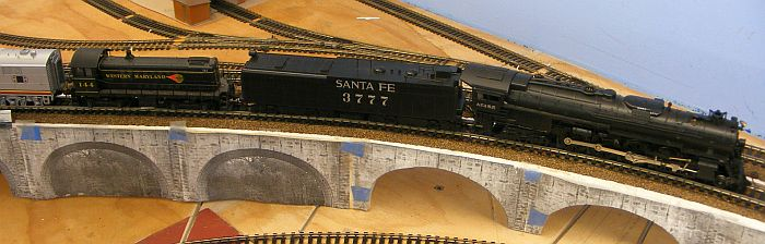
age(325).png

Then behind one of my Mehano mountains,..just plain DC
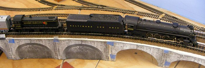
age(326).png
I was really pleasantly surprised. This little Alco diesel model did a great job. I was pulling 20 car trains up the more difficult ramp side of my viaduct,....4.5% grade. It turns out to have a diecast frame that gives it superb weight.

I went onward to try this little diesel by itself. It couldn't quite make it, but it came close.
I then decided to get one of my Bachmann mountains out for a try. A slight problem arose here due to the Bachmann having a DCC decoder installed, so matching the speeds with the pure DC S2 needed a bit more attention. But it also worked extremely well. (BTW I tried the Bachmann mountain by itself, and was pleasantly surprised at its performance. Double heading these Bachmann mountains will definitely be on my list).

I'm convinced that a likely solution for pushing a lot of my steam engines is disguise one of these Atlas switchers into a aux water tender. Sure would save LOTS of custom efforts at adding extra weights to that variety of steamers.
That was posted over here, https://forum.mrhmag.com/post/improving-our-steam-engines-performance-12219656?pid=1331406912


Next came this suggestion from the Prof

Prof_Klyzlr Nov 24, 2021
Replacement sideframes
Dear Brian,
The original Atlas S-series switchers were largely metal, and are standouts in haul capacity. Few contemporary switcher models can match them for "out if box" weight and adhesion. The Kato NW2 might go close?

As for "sneaky sideframes", the Atlas S-series were offered with AAR switcher trucks, which are more "visually non-descript" than the Alco "Blunt trucks". AAR trucks also can be mistaken (from a distance) as express baggage trucks under a boxcar, esp in earlier steam and transition eras

Then Rob in Texas added this,..


I just read through this thread and considered some things that will work for me. I will be building a layout with prototypical grades. Nothing above 1.5 percent and minimum radius of 43 inches scale is HO. I have done some experimenting and found the 2-6-6-6 locomotives to be poor pullers compared to the real thing. There have been lots of good points made about ways to improve this. There have been several comments about why it is not needed because most modelers run 12 car trains or similar points.


This was run after using bullfrog snot and I decided it was unacceptable due to its tendency to clean the rails.
I have discovered that all Steam locomotives are not created equal. I added some weight to some Broadway Limited 2-10-4s and found that they became excellent pullers with out traction tires. As to prototype comparisons the 2-6-6-6s were used in the same territory as the 2-10-4s and pulled the same size trains. It seems to me that pairing a 2-10-4 as a pusher or lead engine and a 2-6-6-6 on the opposite end of the train would be the path of least resistance to sending 100 car hopper trains over the railroad with out issue. The prototype would send 160 car trains over the line with either locomotive unassisted. Another strong puller is their 2-8-8-2 model. A while back they loaded some flat cars with real bricks to demonstrate their pulling power. One of my fellow club members commented that some of those bricks were chipped....

Point I am making is there is more than one way to skin the cat. A weaker pulling model can be augmented by a stronger locomotive. If the train length is long enough the coupler slack will run in and out between the locomotives as each shoulders a different portion of the load and it changes due to the dynamics of the rail line.

Another alternative is the diesel locomotive in the tender shell or a cistern. I am inclined to try this with some models that might not be up to the grade and finding something like an RS1 from Atlas and stuffing it into a 3D printed shell. It might mean adding water bottles to trains that did not normally have them. The advantage is that 2-8-2 might then look good pulling that longer train on the layout and have a much easier time doing so. The mechanism would likely last a lot longer as well.

So the solutions for me add weight if it will work. If it will not work then I will add power in the form of another locomotive, or a powered water car.


How could I ignore these suggestions, and my own experimentation?? I was off on a quest to find the best 'pusher-helper' chassis I might find,.... that already existed,....and a way to disguise it.

 
First Hint of a Powered Tender


Nov 29, 2021
Dummy steam locomotives and powered tenders

I speak about it in my previous post.
This is not often used and most of the time not considered.
But Fleischman has used the trick both in HO and in N scale with their steam model locomotives.
The result are excellent to no say perfect and respectable.
The tender of these locomotives is a powered ones, with four ( most of the time) or six wheel bogies.
the inside of these tender is like a diesel model frame with electrical power on each wheel and motor power on each wheel surrounded by an heavy weight.

The steam locomotives is a real dummy;.... wheels are not motorized and run free pushed or pulled by the tender . There is no gear on the axles, it's a free rolling locomotive.

The boiler is full of weight and contains decoders speakers and all the technical options for the locomotives. All the boiler wheels pick up electricity.

All these models are extremely powerful, some of the tender wheels have sometimes traction tires. They often show power of over 20 streamlined passenger cars on level track , or long freight train even on non- level track.

The same result is obtained on N scale models by Fleischman
In any case these models are smaller steam locomotives besides US counterparts but are far more bigger puller than any U S models in HO or in N scale, .....just with a powered tender and a dummy locomotives.

The approach is poorly investigated, but used by some fellow modeler with excellent results .
In the N scale community this trick was often used in tiny steam locomotives which left plenty of space to put decoder and a big geared motor in the tender.

And if you want to have a monster of pulling, a powered water tender could be added.
Not often used it seems a quiet easy way to obtain a good puller with a steam locomotives.

Marc

************************************


Brian replied,.
Tender Driven Pushers
Actually that Fleismann looks like an interesting approach.

Tender driven pushers with unpowered boiler might make thing a lot less complicated to build,...and likely far less expensive to manufacture? Plus good big space for speakers up in the actual locomotive,...(where the sound belongs !)
 
How do i find out more info on this fellows project?
It does not say the boiler section is un-powered?
In these videos he does. The chassis is built from two Tyco Chattanooga's, which are pushed by the tender.


He does not have a lot of info on his projects, other then what's in the videos. But I have seen him respond to comments sometimes so maybe?
 
Last edited:
BTW I really like this idea, and had planed something like this recently. I am thinking of building a custom flying Scotsman and using one of those Lima shunters. They have proven to be strong and very fast, so I thought this might be cool.

In this video Lima Shunter came on top! 😂


Rivarossi HO y6b 2-8-8-2 Articulate

My initial thoughts were,.. can I get some reasonable expectations from just removing the drive trains and motors from an existing articulate and get it to work??

This older model may have some lessons for us,..


the 2 miter boxes providing the drive shafting down to the tracks


notice that those vertical drive shafts for the rotation center for the fwd truck,...it is located more rearward of the truck’s center,...the opposite of a ‘castor effect’


here I got confused,...a moment ago he was working on the front truck, and noe he is suddenly working on the rear truck??


worm gear down in the truck


Both trucks appear to have their vertical drive shafts (thus pivot points for the trucks) located aft of the center point ??...surprised me.


For our unpowered experiments it appears we just need to remove those miter boxes down in the trucks,...then the trucks should be free-rolling?


Interesting where the rear tender pushing arm attaches,..
https://youtu.be/9vK030RcvTA?t=893


Interesting the down pressure on the leading wheels

(BTW, is there someone out there with one of these locos that is not working for them, that they would provide me with to experiment on??)

...to be continued,..
 
Mantua Experiment

These are pretty neat little locomotives, and relatively simple.


I had forgotten a few things about them,...like the rigid non-rotating back engine, the blind drivers, and the traction tire. I’m glad I have a selection of these locos in very states of disrepair to play around with.

DSCF0238.jpg

DSCF0236.jpg

….blind drivers, traction tire

DSCF0239.jpg


…..connecting drawbar (more on that later)


Drive wheels in bearings of trucks, ….pretty simple design that should be valid for our un-powered version. In this case I would really think that spring suspension of those drive wheel sets was unnecessary,...and particularly since we are NOT looking for any active traction from these drive wheels,...and relatively short overall length of the driver chain,...and the blind driver in the center.

DSCF0240.jpg
Items such as these should make the design of a new un-powered articulate both simpler and less expensive.


In all of the production locos the driveline connection between the 2 trucks(engines) was via a plastic tubing. Its been suggested that this tubing be replaced by NWS universal type components. At first I thought this was a good idea, but I am having second thoughts.


Why would I be concerned about this positive drive component since I am seeking an un-powered chassis?? Looking closely at the situation, that front truck is ONLY attached to the chassis by 2 means,...the drawbar, and that plastic tube between the 2 gear towers. If we remove one of those connections (no tubing in our un-powered articulate), then that leaves ONLY the drawbar...problems ??


I’ve discovered what I think is a problem with that drawbar connection in both the powered and unpowered versions. Have a look at how that drawbar fits down over its attachment pins,…
DSCF0242.jpg

…..naturally we want it to allow free swinging, but it also allows allows excessive vertical movement between the 2 trucks.

I wonder why they provided excessive pin length for the drawbar it fir over? I decided to try and remedy the situation by providing some sort of washers to make the drawbars just swing and not move up and down on those receiver pins. I had trouble finding washers big enough to fit over those pins while not interfering with a ridge on the trucks body. I ended up utilizing the ‘ends’ of some old couplers that I filed out slightly to fit over those drawbar pins, then cut the remainder of the couplers off to leave just a ‘washer’ of a nice thickness to make the drawbars fit better.


I think this might be a solution any rebuilder of these Mantuas should consider?
 
BTW, This first experiment was a Success ?
I've run this unpowered Mantua chassis around my the upper deck of my layout with only one of my Kato pushers pushing it and a bunch of Santa Fe passenger cars following.
DSCF0258.jpgDSCF0259.jpg

I did it with both my 2 different pushers,...shorter one here,....
DSCF0261.jpg


Then I took that unpowered articulate down to a section of my trackplan that has some challenging turns and dbl-curved turnouts, and hand pushed back and forth thru those obstacles,.....NO DERAILMENTS !!
 
BTW, This first experiment was a Success ?
I've run this unpowered Mantua chassis around my the upper deck of my layout with only one of my Kato pushers pushing it and a bunch of Santa Fe passenger cars following.
DSCF0258.jpgDSCF0259.jpg

I did it with both my 2 different pushers,...shorter one here,....
DSCF0261.jpg


Then I took that unpowered articulate down to a section of my trackplan that has some challenging turns and dbl-curved turnouts, and hand pushed back and forth thru those obstacles,.....NO DERAILMENTS !!
Hurrah! Now we know it works!
looks great, can not wait to try myself!
 
Design Considerations to Build a Cheaper Articulated Loco


What if Questions? I want to compose these questions by looking at how one of the better (best) production articulates might have a runner-up product at a much cheaper production cost.

The Broadway Limited 2-8-8-2 is a marvelous creation of design engineering & build quality. I love mine, but for one fault,..later.


Its a pretty heavy engine with its boiler and truck frames built of casted metal. My first question is it cheaper to build these parts of cast metal rather than plastic injection? We do know that the heavy loco will have more traction power, but do we need that sort of traction power on an un-powered articulate?

Could the un-powered articulate have a plastic shell with the extra weight disposed into its voluminous interior via traditional lead weights? Perhaps the trucks themselves could be metal to assist in tracking well?


The BLI trucks are marvelous creations, but I think the un-powered version could have a much simpler design,...like these mentioned above

DSCF0240.jpg
simply straight axles laid into simple full or partial bearings,...and of course no need for that gear.


Here is the BLI truck,..
DSCF0263.jpg

DSCF0265.jpg
.......twin traction drivers, spring suspension, and somewhat complex bearing boxes.

No wonder this loco has so much pulling power, its got 2 traction tires per truck,..4 in all. Of course we all know how much traction tires are adored by many members??


Those axle bearings are both complicated in their shape, and a complicated retainer shape needs to be provided in the truck frame.


I’m really beginning to question spring suspension, ….more so in such a short in-line driver configurations we see with 3 or even 4 drive axles per truck?? And if still desired, could we use a single spring located at the center of one axle on the truck?


Look at what is crammed into the boiler section of that BLI loco,..

DSCF0266.jpg

DSCF0267.jpg

DSCF0269.jpg

DSCF0272.jpg
And its a job to get the top portion of that shell down over that and screwed into position. Let alone there is no boiler barker nor other primary speakers in there. There is no keep-alive, etc.


What if that motor and its gear towers were to be removed from that boiler and put into a pushing tender?


And last, how about servicing? It turns out BOTH of the drive gears in mine are cracked,..

DSCF0275.jpg

Can you imagine what a headache it is going to be to replace them !!
 
SURPRISE !
I've pushed another un-powered articulate around my layout, and it went very smoothly.

It was the Broadway 2-8-8-2 that I had previously noted had a cracked drive gear in the rear truck. I had subsequently discovered it also had the same cracked gear in the fwd truck. Fortunately BLI had replacement gears available for these engines, and I had already obtained some a few weeks ago.

So I decided to just remove that other faulty gear effectively making that loco an un-powered articulate,.... (both faulty gears removed) .
My removal process was to complete the crack in the gear, then remove the 2 half's of the gear. In other words I did not have to go thru the process I will eventually have to do to put the replacement gears in place.

I was pleasantly pleased with the free-wheeling movement of the un-powered loco, and even more so the pushing of it.


The one important thing I have learned is i am going to have to provide traction tires on whatever pusher tender I use,... my disguised Kato pushers experienced slipping wheel traction when trying to concurrently pull those 11 passenger cars.
 
Last edited:
I went out to the shed layout a few hours ago to do a little more 'testing' of that BLI 2-8-8-2. This time i wanted to see how if reacted to some even tighter turns. But those turns are down on the main level that is DCC operation, and nether my pusher, nor the articulate are dcc operated at this time.

So it became a hand pushing back and forth operation thru some rather tight turns with double radi curves mixed in. there are even a few spots where the radi gets down to close to 19-20 inches. It performed very well, with no derailments !!. And surprisingly, no rod binding on that BLI loco that does NOT include a lot of athwartships play with its drive wheels,...really surprised me again,..

DSCF0278.jpg

DSCF0279.jpg

DSCF0280.jpg


Here is that BLI engine being pushed by one of those Kato pushers
DSCF0281.jpg
 
Last edited:
I went out to the shed layout a few hours ago to do a little more 'testing' of that BLI 2-8-8-2. This time i wanted to see how if reacted to some even tighter turns. But those turns are down on the main level that is DCC operation, and nether my pusher, nor the articulate are dcc operated at this time.

So it became a hand pushing back and forth operation thru some rather tight turns with double radi curves mixed in. there are even a few spots where the radi gets down to close to 19-20 inches. It performed very well, with no derailments !!. And surprisingly, no rod binding on that BLI loco that does NOT include a lot of athwartships play with its drive wheels,...really surprised me again,..

DSCF0278.jpg

DSCF0279.jpg

DSCF0280.jpg


Here is that BLI engine being pushed by one of those Kato pushers
DSCF0281.jpg
Lets GOOOOOO! 👍 😄


Affiliate Disclosure: We may receive a commision from some of the links and ads shown on this website (Learn More Here)

Back
Top
