Ok, so you want to know about relays. This technology is pretty simple. For your application, you want to buy a "Normally Open Time delayed Relay". Once power is applied to the relay, the relay waits 5 seconds or so and flips a switch connecting what ever you want. So in your application, let's think of the relay having two connectors to energize the relay, and two connectors that will complete a circut after 5 seconds. Now all you have to do is to figure out how to energize the relay when the loco is on the isolated track. Not sure if these things are AC and DC, so you may have to use a seperate power supply if not AC. Then wire the AC power from a live center rail to the relay and the other side wired to the center rail of the isolated track. Once you trip the power to the relay, the relay will wait 5 seconds and then power the isolated track. Just make sure the relay is rated for the AC power from the Lionel transformer. Simple huh? I attached a breif on how these relays works, happy reading. Allan
Time-delay relays
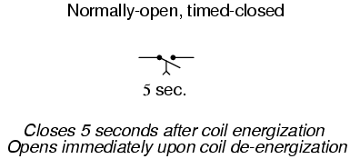
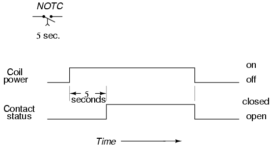
First we have the normally-open, timed-closed (NOTC) contact. This type of contact is normally open when the coil is unpowered (de-energized). The contact is closed by the application of power to the relay coil, but only after the coil has been continuously powered for the specified amount of time. In other words, the
direction of the contact's motion (either to close or to open) is identical to a regular NO contact, but there is a delay in
closing direction. Because the delay occurs in the direction of coil energization, this type of contact is alternatively known as a normally-open,
on-delay:
The following is a timing diagram of this relay contact's operation:
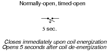
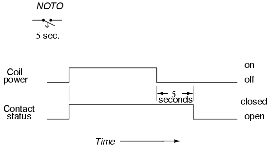
Next we have the normally-open, timed-open (NOTO) contact. Like the NOTC contact, this type of contact is normally open when the coil is unpowered (de-energized), and closed by the application of power to the relay coil. However, unlike the NOTC contact, the timing action occurs upon
de-energization of the coil rather than upon energization. Because the delay occurs in the direction of coil de-energization, this type of contact is alternatively known as a normally-open,
off-delay:
The following is a timing diagram of this relay contact's operation:
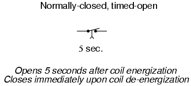
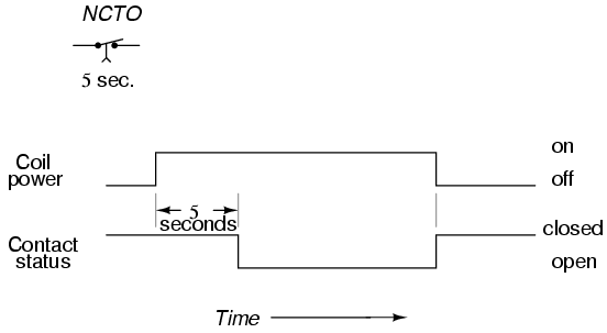
Next we have the normally-closed, timed-open (NCTO) contact. This type of contact is normally closed when the coil is unpowered (de-energized). The contact is opened with the application of power to the relay coil, but only after the coil has been continuously powered for the specified amount of time. In other words, the
direction of the contact's motion (either to close or to open) is identical to a regular NC contact, but there is a delay in the
opening direction. Because the delay occurs in the direction of coil energization, this type of contact is alternatively known as a normally-closed,
on-delay:
The following is a timing diagram of this relay contact's operation:
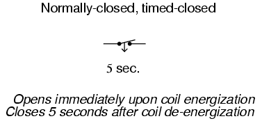
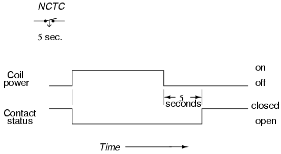
Finally we have the normally-closed, timed-closed (NCTC) contact. Like the NCTO contact, this type of contact is normally closed when the coil is unpowered (de-energized), and opened by the application of power to the relay coil. However, unlike the NCTO contact, the timing action occurs upon
de-energization of the coil rather than upon energization. Because the delay occurs in the direction of coil de-energization, this type of contact is alternatively known as a normally-closed,
off-delay:
The following is a timing diagram of this relay contact's operation:
Time-delay relays are very important for use in industrial control logic circuits. Some examples of their use include:
- Flashing light control (time on, time off): two time-delay relays are used in conjunction with one another to provide a constant-frequency on/off pulsing of contacts for sending intermittent power to a lamp.
- Engine autostart control: Engines that are used to power emergency generators are often equipped with "autostart" controls that allow for automatic start-up if the main electric power fails. To properly start a large engine, certain auxiliary devices must be started first and allowed some brief time to stabilize (fuel pumps, pre-lubrication oil pumps) before the engine's starter motor is energized. Time-delay relays help sequence these events for proper start-up of the engine.
- Furnace safety purge control: Before a combustion-type furnace can be safely lit, the air fan must be run for a specified amount of time to "purge" the furnace chamber of any potentially flammable or explosive vapors. A time-delay relay provides the furnace control logic with this necessary time element.
- Motor soft-start delay control: Instead of starting large electric motors by switching full power from a dead stop condition, reduced voltage can be switched for a "softer" start and less inrush current. After a prescribed time delay (provided by a time-delay relay), full power is applied.
- Conveyor belt sequence delay: when multiple conveyor belts are arranged to transport material, the conveyor belts must be started in reverse sequence (the last one first and the first one last) so that material doesn't get piled on to a stopped or slow-moving conveyor. In order to get large belts up to full speed, some time may be needed (especially if soft-start motor controls are used). For this reason, there is usually a time-delay circuit arranged on each conveyor to give it adequate time to attain full belt speed before the next conveyor belt feeding it is started.
The older, mechanical time-delay relays used pneumatic dashpots or fluid-filled piston/cylinder arrangements to provide the "shock absorbing" needed to delay the motion of the armature. Newer designs of time-delay relays use electronic circuits with resistor-capacitor (RC) networks to generate a time delay, then energize a normal (instantaneous) electromechanical relay coil with the electronic circuit's output. The electronic-timer relays are more versatile than the older, mechanical models, and less prone to failure. Many models provide advanced timer features such as "one-shot" (one measured output pulse for every transition of the input from de-energized to energized), "recycle" (repeated on/off output cycles for as long as the input connection is energized) and "watchdog" (changes state if the input signal does not repeatedly cycle on and off).
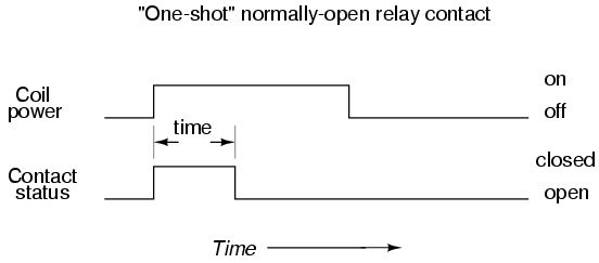
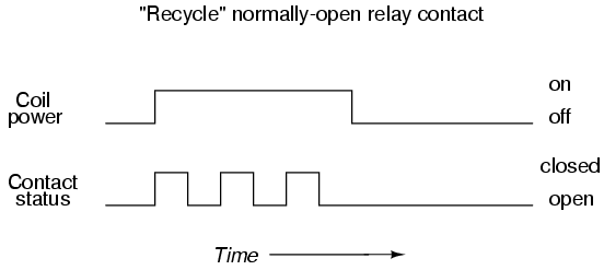
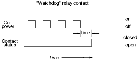
The "watchdog" timer is especially useful for monitoring of computer systems. If a computer is being used to control a critical process, it is usually recommended to have an automatic alarm to detect computer "lockup" (an abnormal halting of program execution due to any number of causes). An easy way to set up such a monitoring system is to have the computer regularly energize and de-energize the coil of a watchdog timer relay (similar to the output of the "recycle" timer). If the computer execution halts for any reason, the signal it outputs to the watchdog relay coil will stop cycling and freeze in one or the other state. A short time thereafter, the watchdog relay will "time out" and signal a problem.
- REVIEW:
- Time delay relays are built in these four basic modes of contact operation:
- 1: Normally-open, timed-closed. Abbreviated "NOTC", these relays open immediately upon coil de-energization and close only if the coil is continuously energized for the time duration period. Also called normally-open, on-delay relays.
- 2: Normally-open, timed-open. Abbreviated "NOTO", these relays close immediately upon coil energization and open after the coil has been de-energized for the time duration period. Also called normally-open, off delay relays.
- 3: Normally-closed, timed-open. Abbreviated "NCTO", these relays close immediately upon coil de-energization and open only if the coil is continuously energized for the time duration period. Also called normally-closed, on-delay relays.
- 4: Normally-closed, timed-closed. Abbreviated "NCTC", these relays open immediately upon coil energization and close after the coil has been de-energized for the time duration period. Also called normally-closed, off delay relays.
- One-shot timers provide a single contact pulse of specified duration for each coil energization (transition from coil off to coil on).
- Recycle timers provide a repeating sequence of on-off contact pulses as long as the coil is maintained in an energized state.
- Watchdog timers actuate their contacts only if the coil fails to be continuously sequenced on and off (energized and de-energized) at a minimum frequency.