ModelRailroadForums.com is a free Model Railroad Discussion Forum and photo gallery. We cover all scales and sizes of model railroads. Online since 2002, it's one of the oldest and largest model railroad forums on the web. Whether you're a master model railroader or just getting started, you'll find something of interest here.
I'll be using NCE DCC for my N Scale layout. There are no reverse loops in my plan, and I'm using only Atlas code 55 #5's and #7's.
I'll have a 2 wire bus under the layout for the track, and I may also have another set of wires to connect to a completely different power source for lighted accessories some day.
I've seen different suggestions all over the 'net, and I'm confused. Also, I'm one of those people who need to see a picture to really 'get it'.
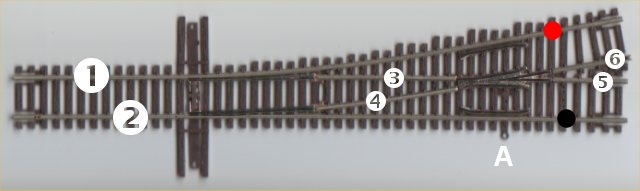
Do I only need to connect 1 & 5 to one side of my bus, and 2 & 6 to the other side?
You're on the right track with wiring the rails in as much as you will not be shorting anything. Example.........all outside rails will be wired to say "black" and inside wires will be wired to "white".......if that was the colors of the wires you used.
"A" on the turnouts is used to power the frog with the proper polarity.........either "black" or "white" depending on the routing of the turnout. I use double pole/double throw switches from Radio Shack to throw the turnout and activate the frog. I believe you could also use single pole/double throw switches to do this as long as you do not plan on using signaling on your layout.
Bob - Thanks for the links. I really like the Tam Valley servo ideas, and the electronics associated on their web site. I think I'll go with those instead of Tortoises.
I'm still not clear on whether I need to power my frogs using 'A' from my picture. Is the only reason to do that for smoother running thought the turnout with older and less reliable equipment?
I'm still not clear on whether I need to power my frogs using 'A' from my picture. Is the only reason to do that for smoother running thought the turnout with older and less reliable equipment?
Basically. Some equipment, especially short wheel base types, sometimes stall on unpowered frogs. The turnouts have small cuts, or gaps in the rails, that isolate the frog to prevent short circuits. Those gaps allow you to power the frog correctly so there will be no short circuits. The alternative is to leave it unpowered, which is what the results will be if nothing is hooked up to "A". If you choose to do this you will need to keep your track and loco wheels a little cleaner to help prevent this problem.
I don't power the frogs on my Atlas Code 55 turnouts. I have #5's, #7's, #10's both left and rights. I also use #2.5 Y's and #3.5Y's. I find I have more trouble with the rest of the turnout not conducting than I have with the frogs not being powered. I have over 100 turnouts in use.
I use Atlas Code 55 turnouts and the Tam Valley Depot system to throw the turnouts.
I make three and only three connections to each turnout as follows.
I connect one bus wire to one stock rail at the location of the red circle. I connect the second bus wire to the other stock rail at the location of the black circle. I connect power for the frog to the point labled "A."
I use the Tam Valley Quad-Pic servo decoder boards to operate servos to throw the turnouts with accessory Relay Daughter Boards to switch frog polarity. The whole system works great.
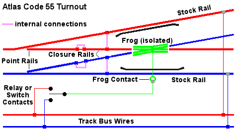
FYI, the Atlas Code 55 turnouts have four built-in jumper wires hidden under the ties that electrically connect different parts of the turnout. These internal connections are shown in pink in the diagram below.
See posts 9 and 10 below for a corrected diagram and information about the internal jumpers.
Some modelers add their own jumper wires in the same locations as added insurance should the built-in jumpers ever fail. I have not done this, but only time will tell if I eventually regret not doing it.
I strongly recommend powering the frogs. It is not hard to do, and it's one less place for trains to stall.
Thanks everyone. At the very least I'll drop a feeder from 'A' while building the layout. When I add the controls I'll wire them up.
It may be a little overkill, but it doesn't seem like a lot of extra work, and if I'm going to do 'overkill' on something it might as well be on the track.
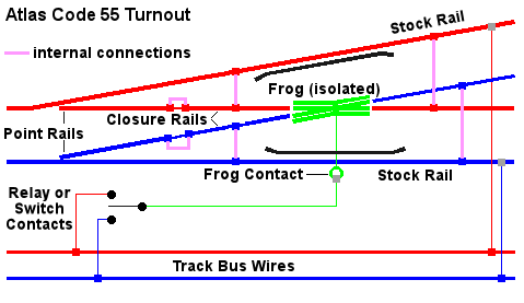
Sorry for resurrecting such an old thread, but I wanted to correct this statement in Jeff's otherwise very excellent post. There are actually SIX built-in jumpers on Atlas C55 turnouts. In addition to the 4 shown by Jeff, there are two additional jumpers between the stock rails and the rails exiting the frog. Referring to the numbers in Jeff's diagram, rail 1 is jumpered to rail 5, and rail 2 is jumpered to rail 6. If you fit insulated rail joiners on rails 5 and 6 (as you might with DC/block-control wiring), then having these jumpers fail can be quite a problem.
I have a couple of turnouts where one or both of these jumpers has failed, and I had to install my own, as shown here. The built-in jumpers are also visible next to the ones I installed.
Before installing Atlas C55 turnouts I now solder my track power feeders (droppers) to both the stock and closure rails from below (rail 1 bridged to rail 3, and rail 2 bridged to rail 4) as shown here. With practice, it takes only a few minutes per turnout to do this.
Thanks for providing the correct information about the internal jumpers built onto Atlas N-scale Code 55 turnouts. I have posted a corrected diagram below.
Though I was well aware of the additional jumpers, I had a brain fade when I created the illustration. There indeed SIX internal jumpers in these turnouts!



 with wiring the rails in as much as you will not be shorting anything. Example.........all outside rails will be wired to say "black" and inside wires will be wired to "white".......if that was the colors of the wires you used.