Green Mountain Railroad Layout Build

ModelRailroadForums.com is a free Model Railroad Discussion Forum and photo gallery. We cover all scales and sizes of model railroads. Online since 2002, it's one of the oldest and largest model railroad forums on the web. Whether you're a master model railroader or just getting started, you'll find something of interest here.


This may a bit late, but you might be happier with a different style hinge. Granted, I haven't see your full plan yet, so it may work out just fine, but with the standard style door hinge you have, your track may pinch into itself when you go to raise the bridge. I use the hinge style for flush mount cabinet doors for my lift gate and they have worked out great.

As for connecting the sections, I'm using 6" sections of flex track - 3" on each side of the break. So far it seems to be working.
 
This may a bit late, but you might be happier with a different style hinge. Granted, I haven't see your full plan yet, so it may work out just fine, but with the standard style door hinge you have, your track may pinch into itself when you go to raise the bridge. I use the hinge style for flush mount cabinet doors for my lift gate and they have worked out great.

As for connecting the sections, I'm using 6" sections of flex track - 3" on each side of the break. So far it seems to be working.
I looked into other hinge types and decided to combine this type with a rail modification like the photo below:

IMG_8889.jpeg


I was thinking I’d cut the track at an angle at the hinge point and glue in some guide rails to keep the rails aligned. Still need to test this concept but I saw some similar designs elsewhere on the internet.

Also, I could be mistaken but since the hinges are above the height of the rail, there should be minimal interference when lifting and lowering the gate. Again, need to test this idea but it seems plausible.
 
Last edited:
You're overthinking this again. You keep saying you're not an engineer, but.....😁


You're overthinking this again. You keep saying you're not an engineer, but.....😁

I promise I’m not haha.

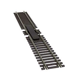
Interesting product! Unfortunately since it’s a straight section and cannot flex, it won’t work for my situation. At least I don’t believe so.
 
I looked into other hinge types and decided to combine this type with a rail modification like the photo below:

View attachment 212283

I was thinking I’d cut the track at an angle at the hinge point and glue in some guide rails to keep the rails aligned. Still need to test this concept but I saw some similar designs elsewhere on the internet.

Also, I could be mistaken but since the hinges are above the height of the rail, there should be minimal interference when lifting and lowering the gate. Again, need to test this idea but it seems plausible.
Before you cut the rails, replace each tie nearest the cut with a pcb tie. Solder the ties to the rails
and then make the cut. Don't forget to remove some copper at the center of the ties to prevent
a short circuit across the rails. The soldered rail to tie connection makes for a robust connection
maintaining rail alignment.
 
Took some time today to get the rivers carved out so I can adhere the foam boards to the plywood.

IMG_8892.jpeg


This part of the river will be more shallow than the other part. My plan in the future is to line the riverbed with a thin layer of plaster and sand to a smooth finish before painting the bottom black and using Woodland Scenics realistic water.

IMG_8893.jpeg


This portion of the river will be slightly deeper and will be filled with a variety of rock work to simulate a dried river bed. I didn’t carve the portion closest to where the backdrops will be since I plan to make a scratch built dam and/or hydro power station. I may make this part wider towards the module joint but I’m not sure yet.
 
Time for another layout update! I’ve completed the backdrop installation. As you can see, I’ve opted to not round the corners of the backdrops but keep them straight. The primary reason for this was due to space constraints in the corner of the layout where the locomotive shop will be.

IMG_8949.jpeg


IMG_8950.jpeg


IMG_8951.jpeg


I still need to add an extension of the backdrop to hide the opening from where the river cuts through the foam.

I also began adding the fascia. This has proved to be a little tricky for two reasons. The first reason is that the warped board mentioned previously and therefore the final alignment of the foam board made cutting and positioning the fascia difficult on the first module. The second reason is another poor design choice on my part.

IMG_8954.jpeg


IMG_8953.jpeg


In the photo above you can see how the fascia panels have lined up. I failed to consider the position of the underlying cross member that the board would screw into. The panel did not come close to the angle required to screw it into the board and therefore the screws were only able to be screwed in so far before beginning to compromise the panel. As of right now, my plan is to not screw in the end of the panel as it’s pretty tight against it with the other adjacent screws. I will try to come up with a solution in the meantime.

The last thing I am contemplating is the positioning of the track near the backdrop. As you can see in the photos below, the track comes pretty close to the edge. Originally the plan called for the tracks to be more centered in the module but by moving the tracks further to the outside against the backdrop, I can increase the size of the track radius.

IMG_8955.jpeg


IMG_8956.jpeg


If I choose to move the track back towards the center of the module, it will only be up to an inch.

That’s all for this week:) I’m hoping to have time this week to finish the fascia but we will see.
 
The track IS too close to the backdrop in your first picture. SIMPLE;) solution is just eliminate that switch so there is only 2 stubs in the corner. You'll have plenty of room to work and it will hold more cars.

Fascia panels look great! Once they are painted black no one will not notice. The focus will be on the trains, not the fascia.
 
The track IS too close to the backdrop in your first picture. SIMPLE;) solution is just eliminate that switch so there is only 2 stubs in the corner. You'll have plenty of room to work and it will hold more cars.

Fascia panels look great! Once they are painted black no one will not notice. The focus will be on the trains, not the fascia.
I was thinking something similar but the only reason I wanted to keep that spur track there is to have a RIP track next to the car/loco track.

If I do remove that spur, I’ll most likely use it as part of the diamond/ interchange setup.

Thanks! Can’t wait to get it painted!


Weekly update time!

The initial fascia construction is complete.

IMG_8968.jpeg


IMG_8969.jpeg


IMG_8970.jpeg


The last section with the sharp curve was the only time I needed to use the ammonia solution to prevent cracking on the hardboard. It worked great!

Eventually I will apply plaster across the backdrop and fascia joints as well as the screw holes to blend everything together so that I can paint the boards.

As you can see in the last photo, I managed to come up with a method to cover the opening created by carving the river.

The first step I did was cut away a small section of the foam to allow a piece of hardboard to fit below the existing hardboard.

IMG_8960.jpeg


I then created some brackets to secure the smaller piece of the hardboard to the framework and also allow it to connect to the existing board.

IMG_8961.jpeg


Here’s the final result:

IMG_8962.jpeg


The riverbed will also be lined with plaster so the small gaps on each side of the smaller piece will be filled.

The last thing I did this week is add an eye hook to the lift gate to be able to keep it upright when not in use.

IMG_8965.jpeg


I just need to adjust a few things here and there and the benchwork will be complete. Next step is adding some plaster to level a few areas in the foam. After that I can start on the track work:)
 
I spent some time this weekend making the initial cuts on the lumber.

View attachment 208970

I also took some time to drill 1” holes into the 1 x 3 cross members to provide a channel for the wires.

View attachment 208971

However, I utilized a spade bit for the first time today and while I did do research on how to use one, I am still getting some slight splintering on either side of the wood. Any ideas?

The last thing I did today was create a mockup with leftover scrap material of what each module joint will look like. I wanted to create one so that I could verify my idea for the module joints would work.

View attachment 208972

The angled section of 1 x 4 on the bottom will serve as the location for one or two carriage bolts to be fed through, allowing each module to be held together.

During the week, i’m going to work on getting some of the rough spots cleaned up on the 1” drilled holes. After that, I’ll begin some of the benchwork construction.
Wish I would have thought of that 20 years ago when I built my frame work
 
The bench work really turned out nice, well done!

I wonder if a mirror in the spot where you put the patch would have made the riverbed look like it went on for a long distance?
Thanks! It’s possible but I’m not sure I could get the right angle to show that given the riverbed is so short on that section.
 
Weekly update time!

The initial fascia construction is complete.

View attachment 213796

View attachment 213797

View attachment 213798

The last section with the sharp curve was the only time I needed to use the ammonia solution to prevent cracking on the hardboard. It worked great!

Eventually I will apply plaster across the backdrop and fascia joints as well as the screw holes to blend everything together so that I can paint the boards.

As you can see in the last photo, I managed to come up with a method to cover the opening created by carving the river.

The first step I did was cut away a small section of the foam to allow a piece of hardboard to fit below the existing hardboard.

View attachment 213799

I then created some brackets to secure the smaller piece of the hardboard to the framework and also allow it to connect to the existing board.

View attachment 213800

Here’s the final result:

View attachment 213801

The riverbed will also be lined with plaster so the small gaps on each side of the smaller piece will be filled.

The last thing I did this week is add an eye hook to the lift gate to be able to keep it upright when not in use.

View attachment 213802

I just need to adjust a few things here and there and the benchwork will be complete. Next step is adding some plaster to level a few areas in the foam. After that I can start on the track work:)
Your layout is looking great!

Where you have different module sections, there is a simple solution. I just cut off a couple ties on one side and slide the rail joiners all the way back out of the way when I want to remove a section.

I do the same thing on my lift out section. A couple shaved ties can be glued down there.

I wonder if you will have an issue with the hinge on your lift out, curious how you will deal with that geometry, not sure if the beveled track will do it.

Very nice work!
 
Your layout is looking great!

Where you have different module sections, there is a simple solution. I just cut off a couple ties on one side and slide the rail joiners all the way back out of the way when I want to remove a section.

I do the same thing on my lift out section. A couple shaved ties can be glued down there.

I wonder if you will have an issue with the hinge on your lift out, curious how you will deal with that geometry, not sure if the beveled track will do it.

Very nice work!
Thanks!

I’m not sure how I’ll tackle that problem yet but I’ll be working on it soon enough:)
 
The inline 1 inch holes. Seems so obvious now; but it didn't 20 years ago. I was probably in too much of a hurry
I originally didn’t think of it either but I read a book and some additional articles on benchwork during my design phase and learned about the importance of them.

Well if you ever build another layout, now you know to add them into the design. 👍


Not much progress this week unfortunately but I still made progress nonetheless:)

I applied some plaster on the first section of the layout where the foam board was not level. I’ve applied two coats so far and I may apply a third but we’ll see. It’s definitely an improvement over what it was before.

IMG_8987.jpeg


I also applied plaster to the backdrop panel joints and over the screw heads. Needs a few touch ups but it’s nearly there.

IMG_8988.jpeg


IMG_8989.jpeg


As you can see, I also have begun experimenting with scrap foam boards to create some mountains/hills. I was thinking of using a few pieces to make the backdrop mountains in some areas using a vertical technique vs. layering the boards horizontal. I’m not sure about this idea and have never tried it. Any thoughts or feedback?

IMG_8984.jpeg


IMG_8985.jpeg


IMG_8986.jpeg


The last thing I did was to finally get the last two screws and finish washers in place. As mentioned in a previous post, I made a boo boo and didn’t position the underlying cross member in a more favorable position leading to the screws not lining up. I managed to fix this by using some shorter screws and carefully re-drilling some holes.

IMG_8990.jpeg


I will fill in the old holes with plaster before painting the fascia panels.


Affiliate Disclosure: We may receive a commision from some of the links and ads shown on this website (Learn More Here)

Back
Top