ModelRailroadForums.com is a free Model Railroad Discussion Forum and photo gallery. We cover all scales and sizes of model railroads. Online since 2002, it's one of the oldest and largest model railroad forums on the web. Whether you're a master model railroader or just getting started, you'll find something of interest here.
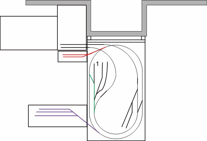
i did not make a more recent drawing. main module is 4x7. the purple setion was canceled, as i found out i was to optimistic about space it will take. the red section (the latest addition) is 7 feet by 11 inches shelf
One suggestion is that you make a turn around for the upper black sidings....
It seems a long road to nowere. You can't really park cars on the approach, because it's on an incline. Just a suggestion....
One suggestion is that you make a turn around for the upper black sidings....
It seems a long road to nowere. You can't really park cars on the approach, because it's on an incline. Just a suggestion....
what do you mean when you say "turn around?"
in any case, the black upper section is not drawn out here. this is earlier diagram showing mostly layout of future modules.
so after taking prolonged break from construction, i'm back at it
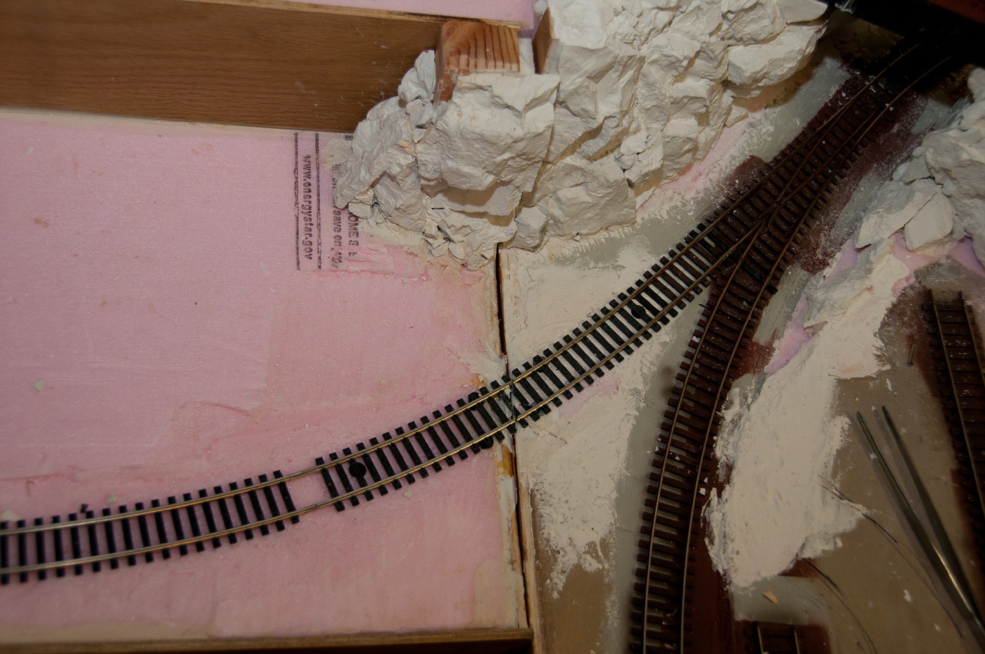
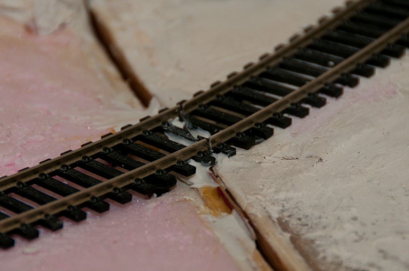
worked on transition between main layout and lower module. and while doesn't seem like much, i spent quite some time figuring out how to acomplish things. results are below for your judgement.
overview
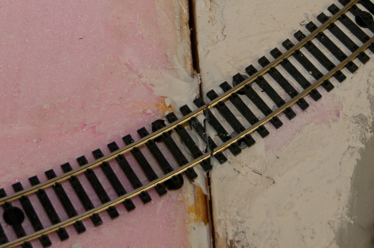
the R22 piece of track is cut at an angle including the tie - managet to not loose lost any pieces of it. for precise positioning i used wood srcrews going through foam all the way into plywood as foundation. each half rests and superglued to 3 screws height of which was carefully adjusted to provide for correct elevation and superelevation. transition through this joint ended up being smoother then with arlas custom #4 turnout frog
another angle
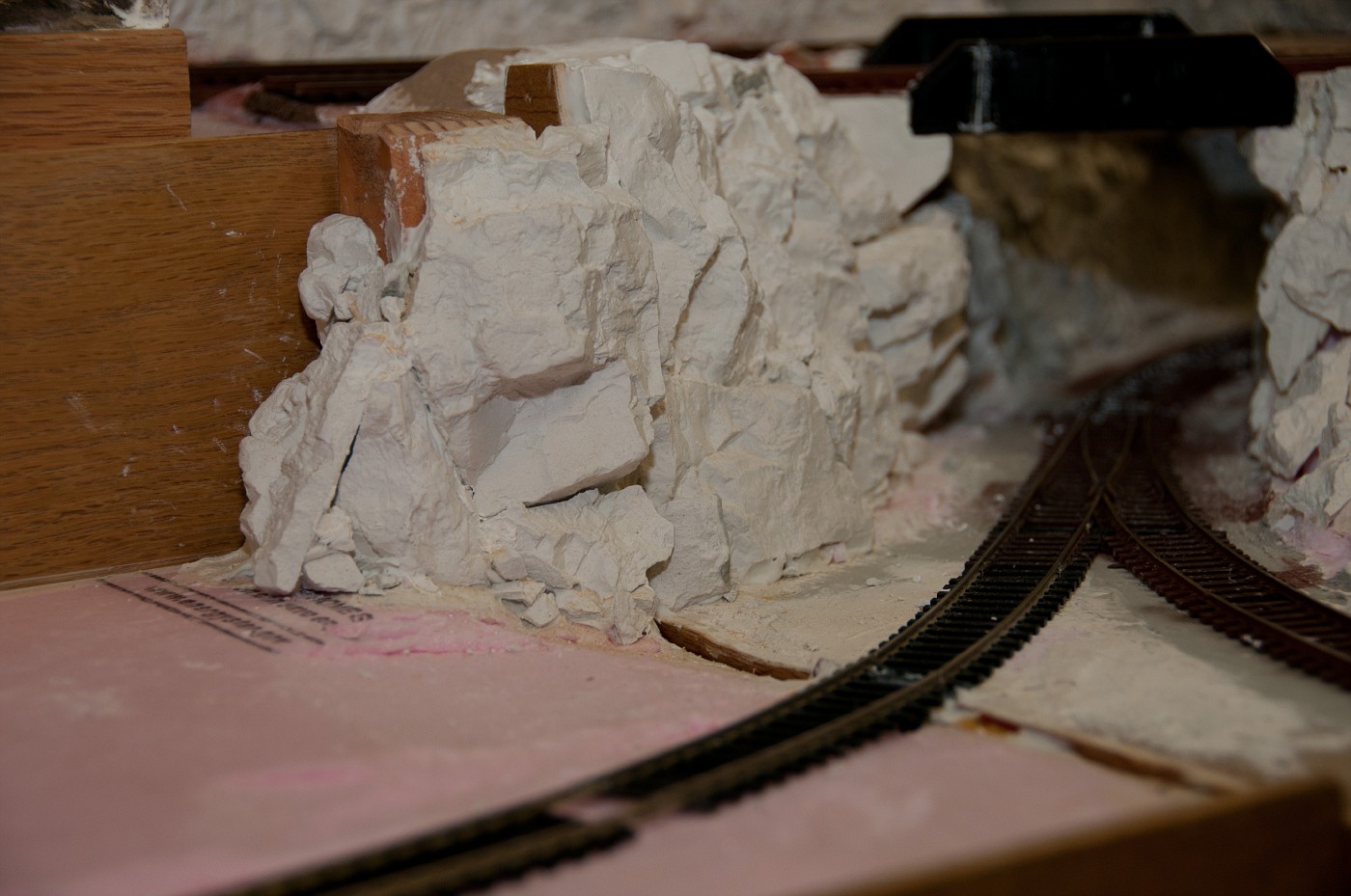
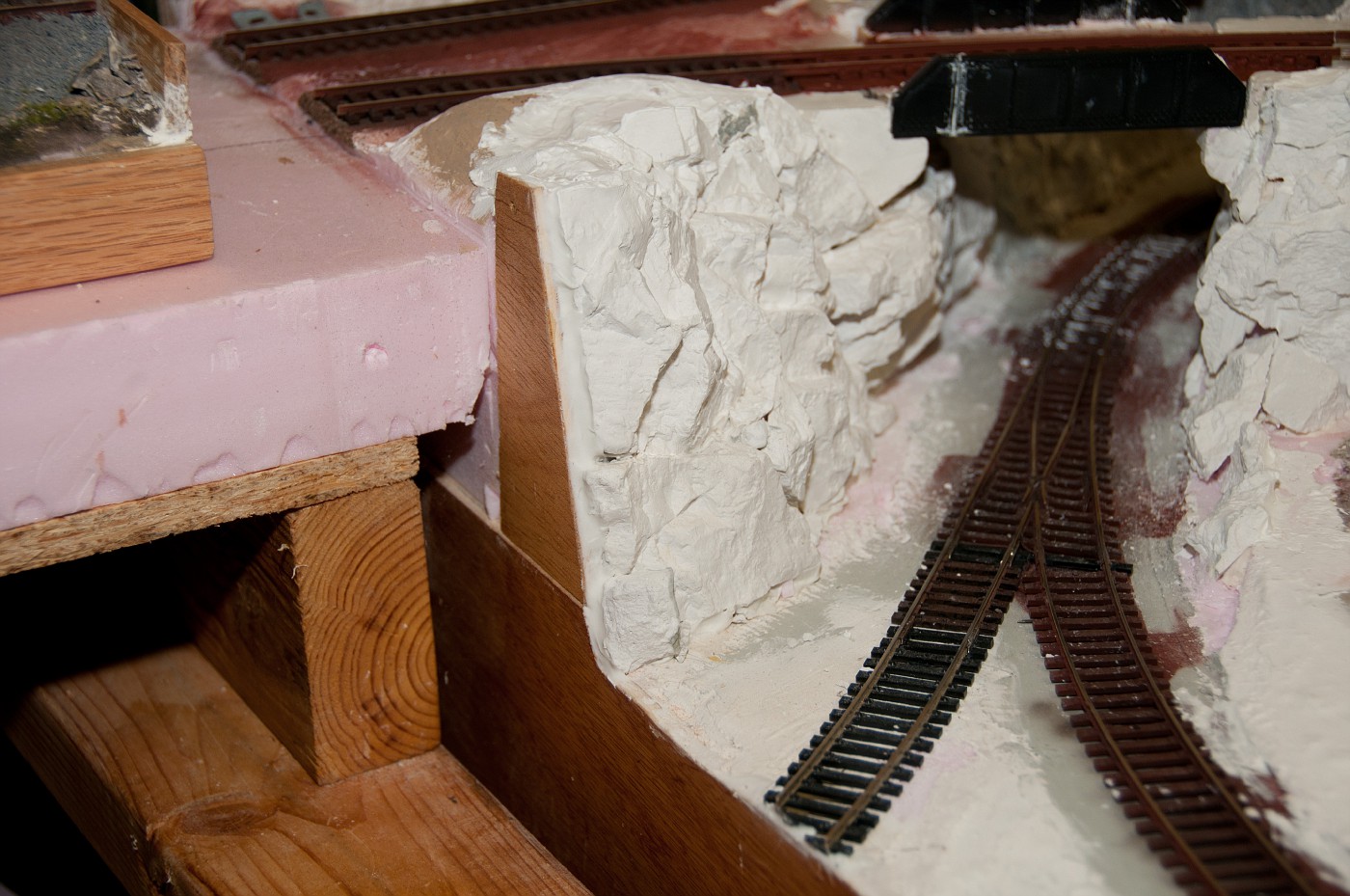
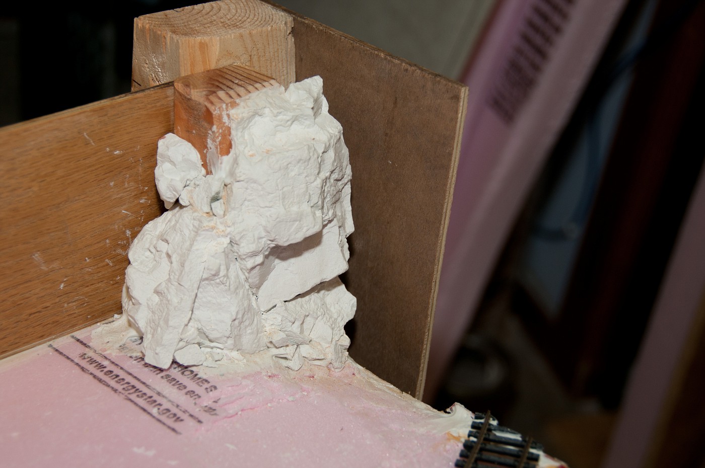
scenery transition is almost invisible from this angle - the cliff is overlapping into main mudule.
but from this angle it is quite bad.(even though it actually looks better in person). still work to be done.
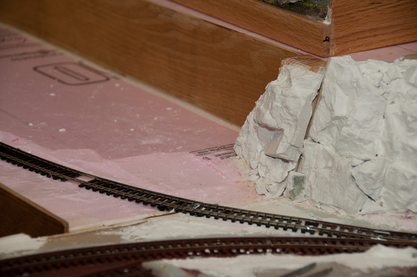
without the module the edge is quite clean
when stored, the fragile edge of overlapping cliff is protected buy detachable cover
EDIT:
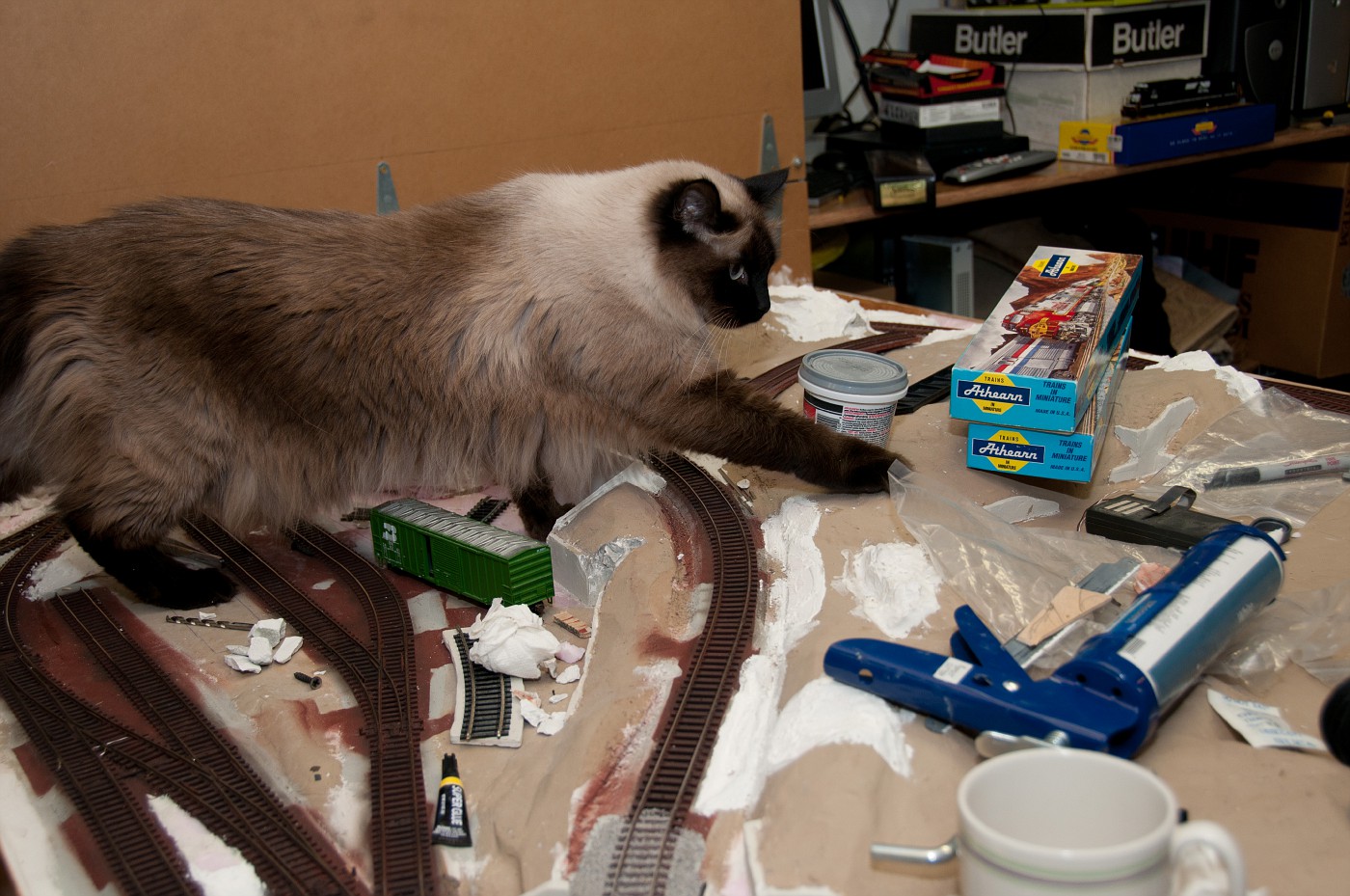
ohhh, almost forgot. got pictures of my layout being raided by Catzilla
Kellan, i looked into making proper end-plates but this is not really full blown freemo module so this will do. besides, adjusting the height and shape of this curve (which is also changing elevation) was a matter of changing height of the foundation screws buy turning them. relatively easy but adjustment can be very precise.
Julien, rail is painted with rustoleum rust primer and then airbrushed with very watered down acrylic brown/black mix. turn a page back to see the stages.
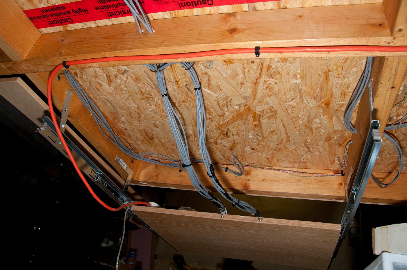
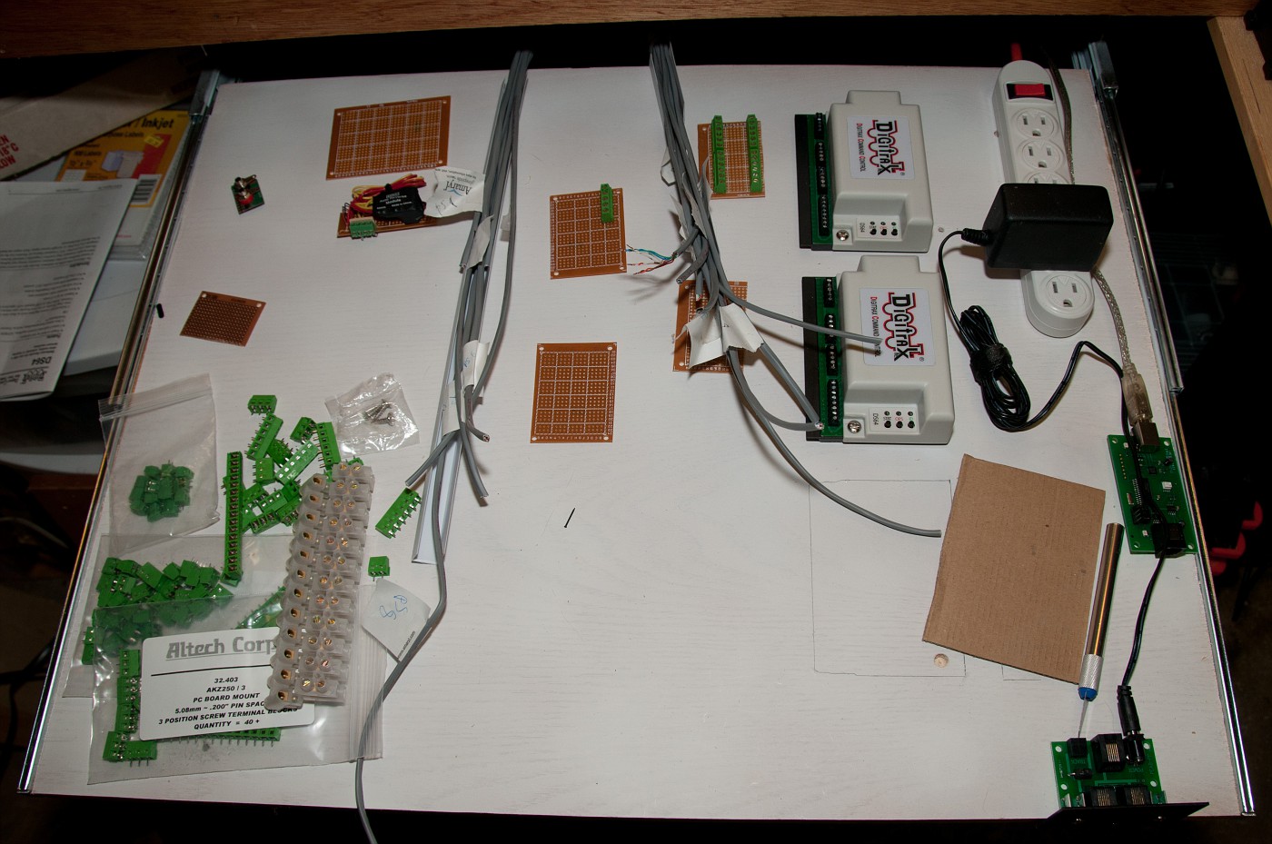
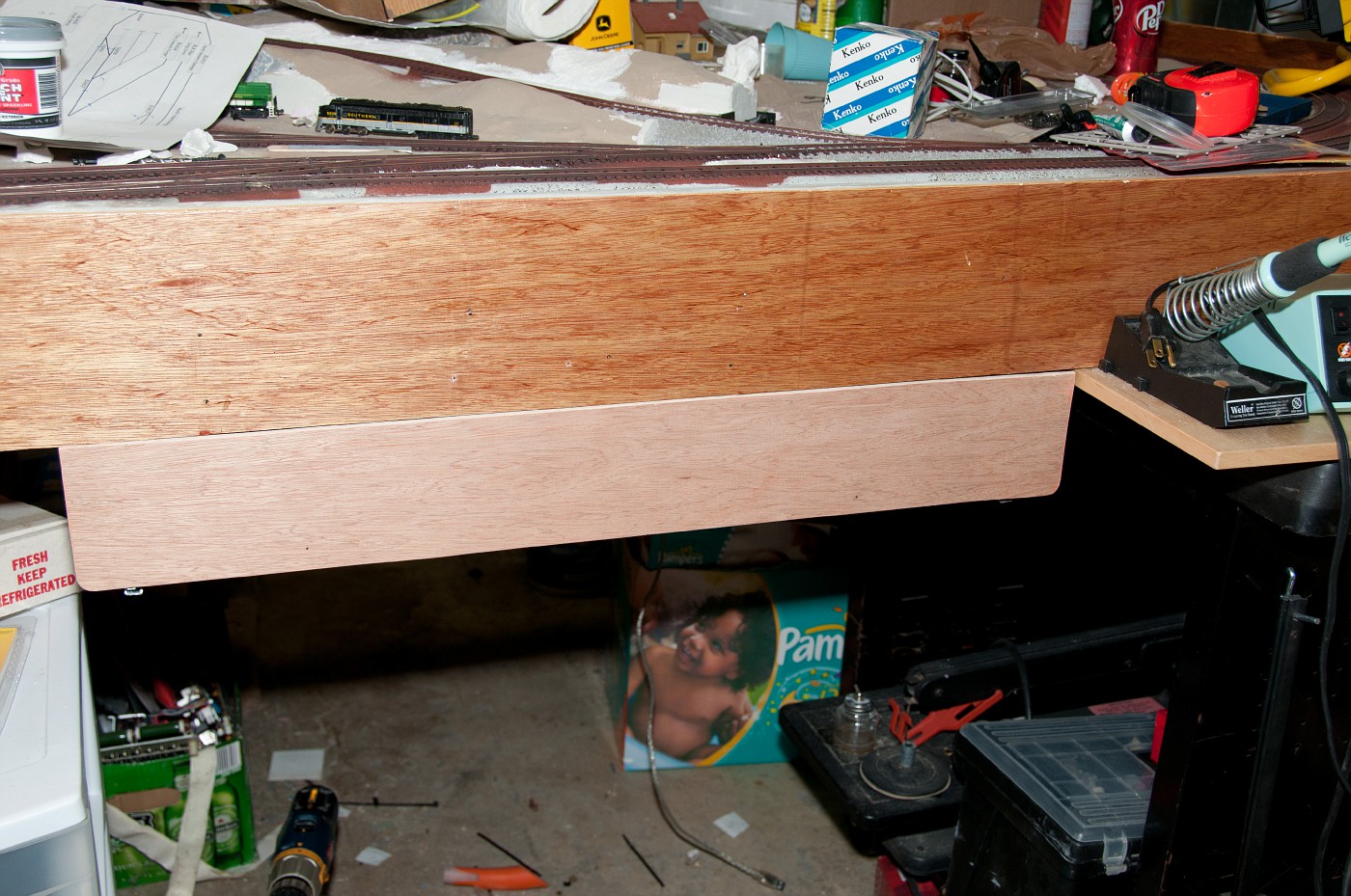
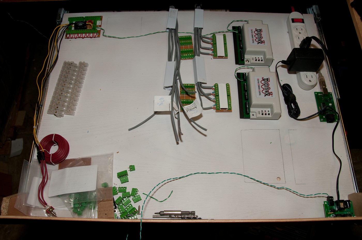
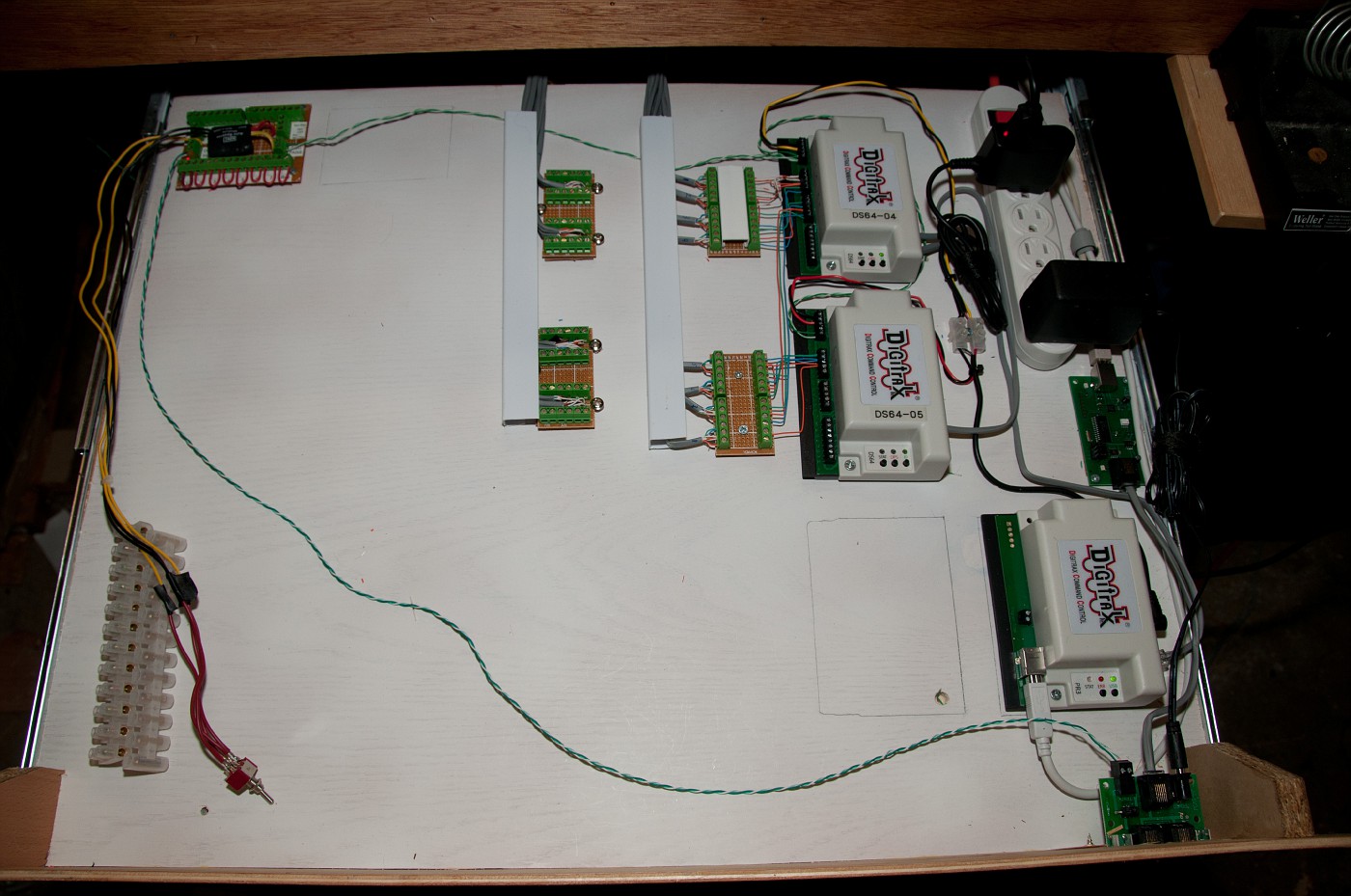
completley redoing my wiring and going all digital. as inspired by REXHEA's solution (linky), i added retractable shelf where all the decoders, block detectors, PC interface and signaling hardware will live. computer will be hung underneath the table as well. shelf instaled and wires run. now the fun of connecting everthing . two DS64's are here, with room for one more and PR3 interface. team digital SRC16 will be used for the next control panel.
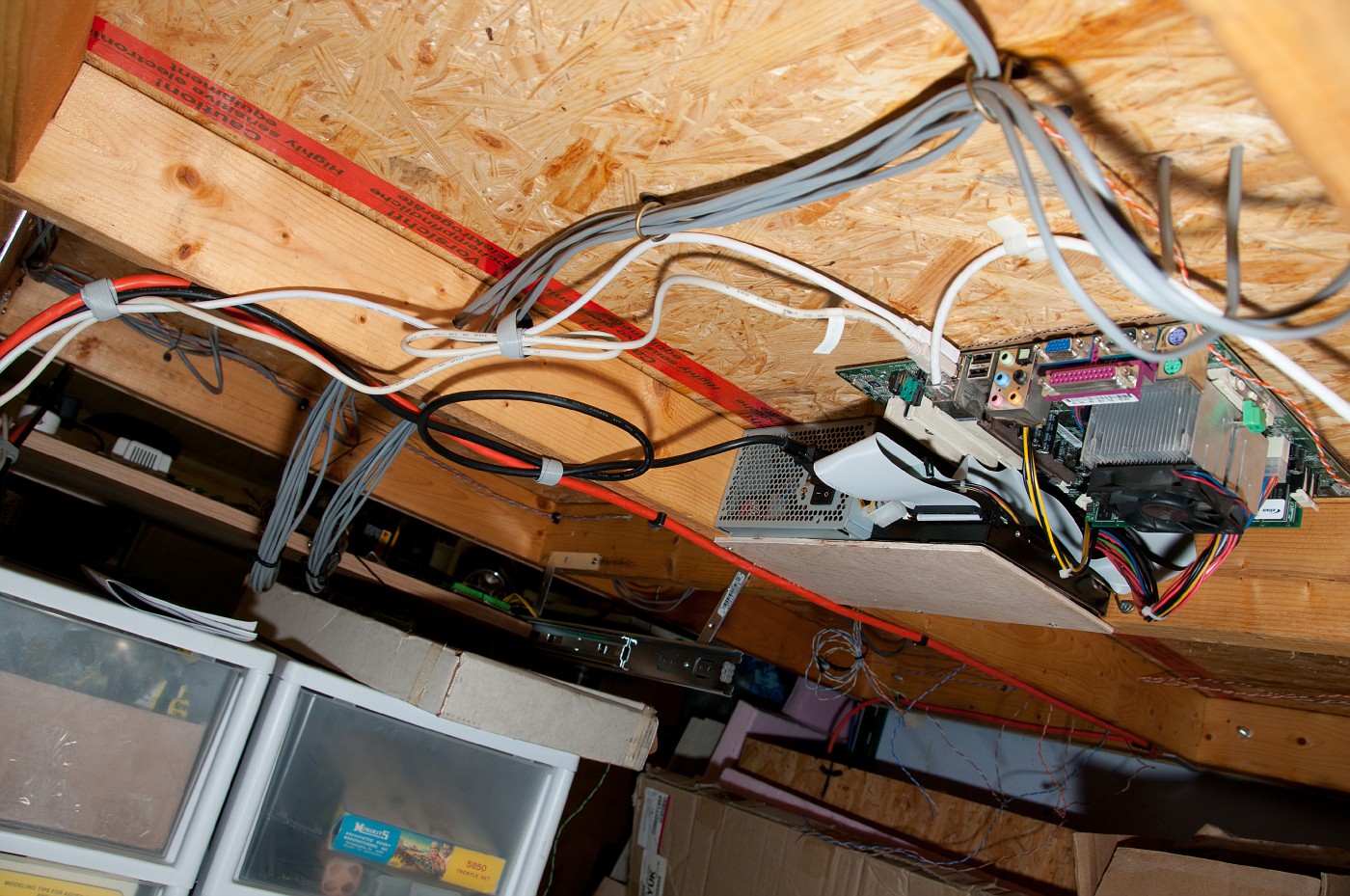
undeneath
shelf open. some supplies
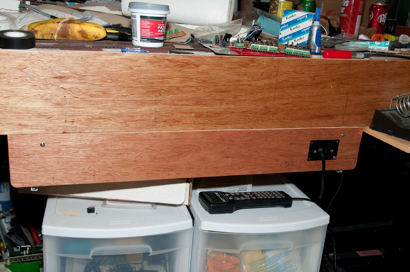
shelf closed. still need to paint the fascia and cut window for NCE faceplate.
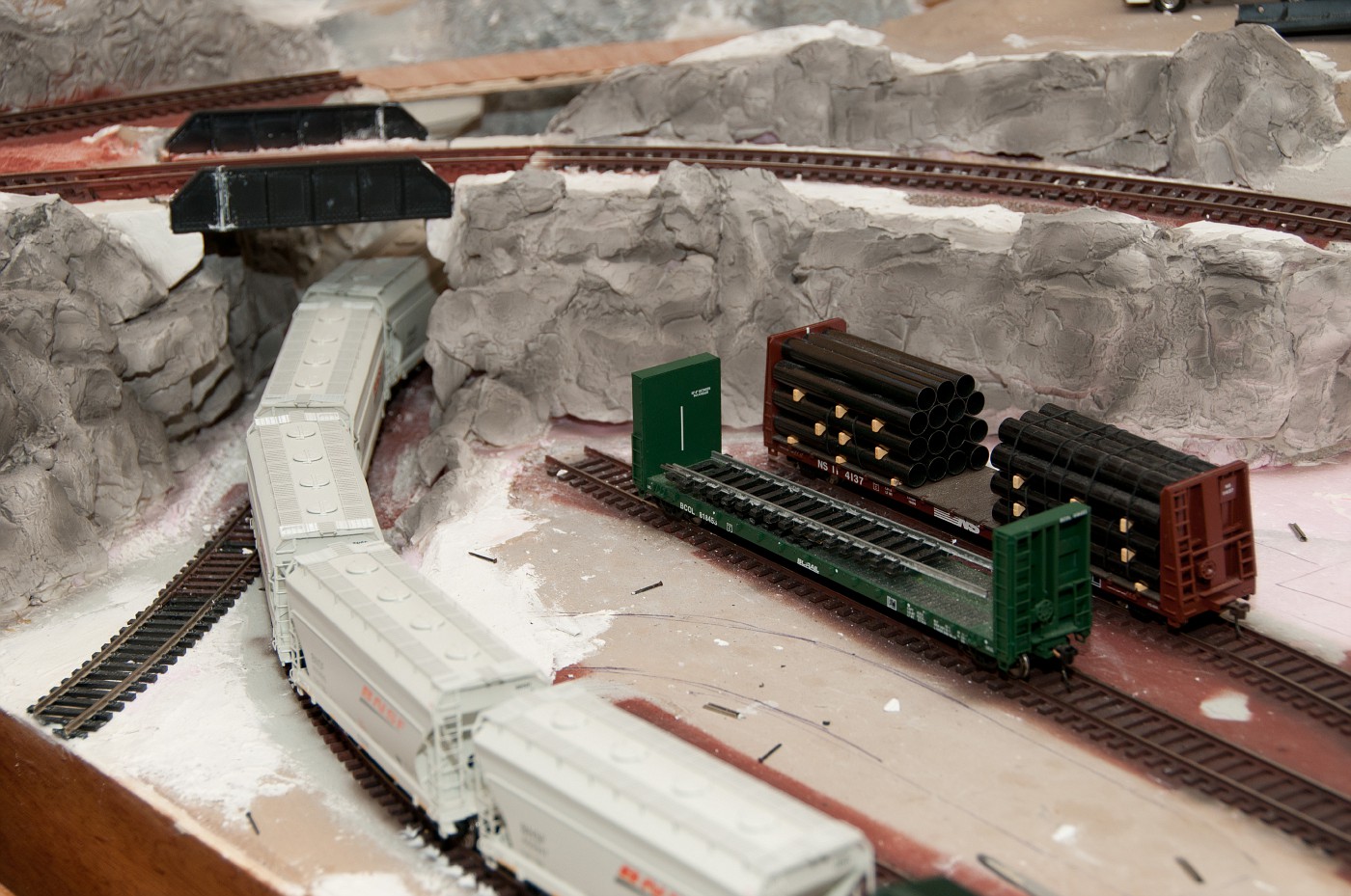
previous picture - rock faces airbrushed with first coat of india ink
moving along.
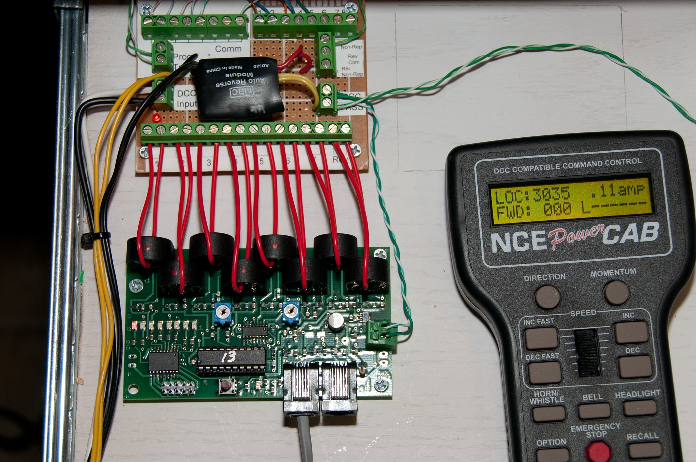
power distribution board created. red jumpers will be routed through block occupancy sensor board (whenever that happens). turnout coil wires terminated. TO sensor wires next. waiting on my PR3 interface
fascia panel mounted and painted. NCE patch panel installed
installed PC that will be Running JMRI under my layout. the compact case eneded up being less compact that i hoped, so instead i just screwed my old Athlon XP board underneath the table and did small shelf for PSU and HDD. it is configured to turn on whenever it has power, later i might throw the On-off button on the front panel.
the beauty of this thing is thati work on it remotely - from warm room
installed JMRI and CATS extension on it already , learning the trade.
so far ease of programming engine decoders is impressive to say the least. no more obscure codes.
Wow, I am a wiring nut. I have to say your wiring is awesome! I would be weary about the PC motherboard being mounted upside down though. Heat soak on the CPU could be an issue.
thanks Brian,
i was thinking about the same thing - heat trapped underneath the table. but this is not high end system, not going to be overclocked nor do any cpu incentive work. even if it is running several degrees hotter then in proper box i'm not going to worry about. right now is near freezing in garage anyways, but for summer, if things go out of hand i will install a fan to move air across the thing.
I'd probably put the board on standoffs from the plywood just to be safe. I don't imagine it'll get hot enough to cause problems, but a little airspace never hurt anything. (Well, except the Death Star, but that's a totally different...)
terminated all the coils and turnout position detectors. crimped loconet and NCE bus cables. split one PS14 powerpack between both decoders and PR3. wired all but the last coils to outputs of respective DS64's.
this is simply awesome! even paired turnouts on single channel are thrown with positive clack. and activating these via PC is even more awesome! here is how things look now (track is still not powered).
one thing bothers me however. DS64 will respond to commands from track bus either directly from powercab or NCE-USB via PC. obviously they respond to their input comands (position toggle). but as soon as i connect them to PR3 they stop accepting comands from track. i can progam opSw on both via PR3 and decoder pro, reading board IDs and opSw's i just set. if i understand anything this means i crimped the loconet cables in correct way. opSw 14 is set to allow commands from both PC and Track (off), which even had it been enabled it still should have accepted commands from track. any idea on this one?
one thing bothers me however. DS64 will respond to commands from track bus either directly from powercab or NCE-USB via PC. obviously they respond to their input comands (position toggle). but as soon as i connect them to PR3 they stop accepting comands from track. i can progam opSw on both via PR3 and decoder pro, reading board IDs and opSw's i just set. if i understand anything this means i crimped the loconet cables in correct way. opSw 14 is set to allow commands from both PC and Track (off), which even had it been enabled it still should have accepted commands from track. any idea on this one?
upon digging more in to it - the way DS64 works is it will only accept commands from rails if loconet connection not present. why wasn't it working from PC then? well, JMRI stores turnouts not only by their accessory address but by system name. in this case LT1 (L - Loconet, T - Turnout, 1 - actual adress). once i tried that everything worked.
populated the rest of turnouts in and was able to switch them all even without punching in numbers everytime.
at least to me it is a real hoot to click a button on screen and hear the turnout click on the layout feedback switches next
questions to those who deal with JMRI however:
i wired two turnouts that make a crossover to one channel to save up on channels. for the purpose of feedback i guess i will need to declare them as two logic turnouts that reside on same accessory address but have separate physical position detection inputs. does it make sence? or how would you deal with turnout position feedback for paired turnouts?
connected the turnout position detector switches to inputs of DS64's, rest of the progress is on the software side of things.
Left all early JMRI attempts behind and started fresh.
programmed decoders with addresses according to new numbering scheme. Entered all the turnouts into table and verified operation. JMRI Sensor table populated all by itself, added annotations to make things more comfortable to work with (system names LS26, LS34 are not really descriptive). Associated turnouts with corresponding sensors. For paired turnouts i used "TWO Sensor" mode. if one fails to trigger the position is shown as inconsistent. in general feedback is a thing of beauty - even if thrown manually the system knows turnout position.
started drawing the panel. cant wait for my touchscreen to arrive.
Entered 2 locos into JMRI Roster. Working with JMRI throttle going to be sweet! however if someone has good JMRI Icon of Norfolk southern GP38-40 let me know (collection i downloaded is missing norfolk southern )
For me this dimension of model railroading is Uber fan







 )
)