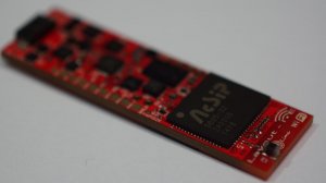
First WiFi Loco-Nodes, ready for fabrication/assembly

ModelRailroadForums.com is a free Model Railroad Discussion Forum and photo gallery. We cover all scales and sizes of model railroads. Online since 2002, it's one of the oldest and largest model railroad forums on the web. Whether you're a master model railroader or just getting started, you'll find something of interest here.


Status
Not open for further replies.
0001_A_zpsf6a31872.png


0001_B_zps0a7cfddf.png


Not enough wires - we need more wires! :rolleyes:


Seriously though - why so many wires? For a fairly typical DCC decoder you would have Power In, Motor Out, Functions Out = 2 + 2 + 1 + #functions.

And without knowing how big that motor is that board looks rather large compared to the DCC decoders I normally use - perhaps too big for HO scale locos?


Enjoying the progress.
 
Yes wires because we haven't made chips small enough to do wireless powered LED's.

This is 30 AWG wire, if you use magnet wire, things are considerably better.

Each pad will support up to 3 LED's.

Why?

Here is a prototype locomotive each bulb housing = one LED:

Headlights - two, up to four
Front Ditch Lights - two
Alternating Ditch Lights - one from above plus another
Step Lights - two
Walkway Lights - one
Number Lights - two
Cab Light - one
Class Red - two
Class Green - two
Class White - two
Mars - one or two
Gyra - one or two
Strobe - one or two
Ground Lights - two
Rear Hood Walkway - two with up to six more if NS
Rear Number Lights - two
Rear Head Lights - two, up to four
Rear Ditch Lights - two
Rear Ditch Lights Alternating - one above plus one
Class Red - two
Class Green - two
Class White - two
Step Lights - two
Plus any rear mounted Gyra, Mars, Strobes

I have to plead ignorance on steam, the pin assignments can be reconfigured for steam operation but I don't know what do for this yet as for assignments.

The width and length of the board are OK for HO scale, not all wires or LED's would be used in a typical application, its there if you want prototype operation
 
Yes wires because we haven't made chips small enough to do wireless powered LED's.

This is 30 AWG wire, if you use magnet wire, things are considerably better.

Each pad will support up to 3 LED's.

Why?

Here is a prototype locomotive each bulb housing = one LED:

Headlights - two, up to four
Front Ditch Lights - two
Alternating Ditch Lights - one from above plus another
Step Lights - two
Walkway Lights - one
Number Lights - two
Cab Light - one
Class Red - two
Class Green - two
Class White - two
Mars - one or two
Gyra - one or two
Strobe - one or two
Ground Lights - two
Rear Hood Walkway - two with up to six more if NS
Rear Number Lights - two
Rear Head Lights - two, up to four
Rear Ditch Lights - two
Rear Ditch Lights Alternating - one above plus one
Class Red - two
Class Green - two
Class White - two
Step Lights - two
Plus any rear mounted Gyra, Mars, Strobes

I have to plead ignorance on steam, the pin assignments can be reconfigured for steam operation but I don't know what do for this yet as for assignments.

The width and length of the board are OK for HO scale, not all wires or LED's would be used in a typical application, its there if you want prototype operation.

This is a smaller motor most, the board is 16mm x 55 mm.
 
I posted a blog entry, just sums up the past weeks in one page. Somewhere along, the recharge rate was defaulted to a full 2 amps in the schematic, so when power was applied, it blew the battery supply inductor and diodes for rail input. Its fixed but with 0201 components, I need to get new boards to test further. Expecting to sign off on them tonight.

Software is in good shape, Juan and I are integrating the control app with the test node.

http://www.layout-ioe.com/blogs/news/15279017-wifi-update
 
Hello,

Here is another video.

We have all four layers of software working.

(1) C# for the front end applications

(2) C#/Linux libraries for the back end application

(3) WiFi mesh

(4) Linux Driver Kernal for the Nodes

C# enables us to develop applications using Android, iOS, Linux, and Windows.

Juan is working on more functionality for the application now.

[video=youtube_share;SpTCoPW6FsE]http://youtu.be/SpTCoPW6FsE[/video]

V1.3 for Loco-Node 0001S is in Fabrication/Assembly.

Based on testing of V1.1, the battery charge system has been updated and USB flashing has been added to end user Nodes to enable rewriting the board if all memory has been erased.

A small batch will be here in a few weeks time.

We've also restarted our drive work to compliment this system.

The first effort is scale HTC trucks with working traction motors. This puts all drive components into scale traction motors.

The new updates will be 3D printed. Here is a test sample we got of the side frame just to see if this is feasible. The test worked.

htc_2_zps581775fb.jpg


htc_6_zps91bed30a.jpg


Here is a great article on the benefits of dead track and battery power/RF control.

http://smallmr.com/wordpress/battery-and-wireless-control-for-ho-scale/

If you take a side by side comparison, here are some facts we have to offer:

Dead track operation

Battery recharge WITHOUT conditioning or removing the batteries

All you need is a Node and control app with the battery if desired

NO DCC, or associated command stations are required

The cost is limited to the Node and software, other systems, you need the RF equipment AND DCC decoder + DCC command control system.

Christopher Howard, Phoenix-Micron Inc.
www.layout-ioe.com
 
Last edited by a moderator:
[video=youtube_share;licP6MA4j6w]http://youtu.be/licP6MA4j6w[/video]

This video shows PWM being controlled by an Android device.

The PWM has two assigned output channels for special light effects. You wouldn't actually control them as seen in this video as the software would be either ON/OFF. A Mars or Gyra light would be an example of PWM for LED control.

As seen in the video we used a slider to control the brightness of the LED.

The direction application for this is motor control.

The PWM signal in the production boards goes to an H-Bridge which is essentially a switch. It enables precise control of the motor and also gives full motor rated torque at all speeds.


Here is another video showing the "dim" button

[video=youtube_share;b-qy0FWJMzo]http://youtu.be/b-qy0FWJMzo[/video]

We're on track to have the basic application completed this week, sound is also up and running

Fabrication of the new boards has started
 
a new production with all revisions is leaving our supplier on the 20th of October, will be able to install in some locomotives then, the last batch didn't have enough samples remaining after testing to do this
 
I am just starting to read your site, but it seems like it keeps saying the motors you control are 6V. Are all standard loco motors 6V? I also note that you do not need DCC, what if we already have a DCC controller? Will this system be able to accept power from a DCC controller, or do we need to swap out to a DC power pack for the track?

Just to be perfectly clear for me, I would take an existing engine, rip out my DCC decoder, install this and apply DC to the track, add in my Wifi and go? I like that it is running linux, how long does it take to "boot" to a state where you can drive the engine? I looked around your website, but the product pages did not answer these questions. Thanks.
 
I am just starting to read your site, but it seems like it keeps saying the motors you control are 6V. Are all standard loco motors 6V? I also note that you do not need DCC, what if we already have a DCC controller? Will this system be able to accept power from a DCC controller, or do we need to swap out to a DC power pack for the track?

Just to be perfectly clear for me, I would take an existing engine, rip out my DCC decoder, install this and apply DC to the track, add in my Wifi and go? I like that it is running linux, how long does it take to "boot" to a state where you can drive the engine? I looked around your website, but the product pages did not answer these questions. Thanks.


LN0001S and LN0003B are Loco-Nodes with Li-PO battery management, this is intended for HO/S scale with 6 volt motors as the batteries are 7.4 Volts.

You can power up to 6 motors.

This will work with our traction motors or the 6V can motor we have posted.

It will also work with existing motors in RTR which are 12V rated, the difference though is the 6V motors I sell are wound differently so their starting voltage is much lower and smoother.

LN0002S and LN0004B are Loco-Nodes without any battery management. They are direct DCC replacements and need continuous track power for operation.

Power can be 13.5V - 24V DC or 13.5V - 18V AC. So it is compatible with existing DCC power supplies.

The battery management system will use that input to recharge the battery.

Battery recharge can be done without removing the battery.

If you strategically place recharge areas on your layout, you can run with dead track if you have the battery type nodes.

Otherwise for the no battery installation, just keep constant power to all of your track.

The nodes will be in a constant low power sleep mode unless active. Wake up time is a few milliseconds.

All of the communication is direct and wireless, no DCC command station or components are needed to use the nodes.

Thanks,

Christopher Howard, Phoenix-Micron Inc.
www.layout-ioe.com
 
We tested the boards successfully up to the full rated voltage without any faults or burned up components.

I got results back from an audit of our voltage readings and we're safe to install the Li-PO to the test board.

This will provide adequate current to get the voltage regulator output up to system requirements.

Thus all of the power supplies and distribution work, next task is to flash the SPI NAND Flash so we can use the CPU.

At this point, looks like we're ready to start shipments very soon.

board_zpscc9e9386.jpg


IMG_20141110_205820_zpse6c4171e.jpg


Christopher Howard, Phoenix-Micron Inc.
www.layout-ioe.com
 
November was lost to a lot of time on the road and personal reasons, but by the end of today we're likely to have a working board we can show after some handwork

Nothing was wrong with the last batch except we needed to replace the recharge current resistor with a different value, remove one, and add two capacitors not added during SMT

The board design is good, just a hick up with the first 8 we made of the V1.3 design during assembly

I posted some initial hardware integration instructions on our Facebook Group, Phoenix-Micron Inc. and Layout-IoE

The UI will have a wizard that walks you through set up so the manual just covers wiring and regulatory will be added later once I review what needs to be added

There are 5 LN0001S Nodes available to ship immediately after these hand fixes, more will go on order with our supplier once sales start

LN0004B is up next to go. There is a few changes made to simplify things in V1.4 but from an end user standpoint, you will not know the differences

LN0001S is designed for dead track operation, and will recharge when voltage is applied to the rail inputs

LN0004B is designed for consistent voltage on the rail inputs, similar to a normal decoder

With LN0001S cleared, its the "father" for the other variations as they are created by removing items, the hardware aspect is completed

This an numerous other products are in stock and on our web-site, www.layout-ioe.com

013.jpg
 
I love this idea but I am wondering why not choose a single cell lipo
battery?

A small voltage booster to bring the voltage up to 12v
so a standard loco does not need to be re-powered ?
http://www.pololu.com/product/2117

Battery charging is simplified without having to balance charge
cells and no need to re-power the loco.

 
I love this idea but I am wondering why not choose a single cell lipo
battery?

A small voltage booster to bring the voltage up to 12v
so a standard loco does not need to be re-powered ?
http://www.pololu.com/product/2117

Battery charging is simplified without having to balance charge
cells and no need to re-power the loco.

The on-board battery charger circuit is no different for a single or multiple cell battery in regards to effort. Most IC options are for multiple chemistries and cell quantities.

Li-PO's are made by combining 3.7V cells so a single cell at best is 3.7 volts.

Boosting this with a power supply is going to limit run time considerably going up to 11 volts.

Thus with dead track, using 6 volt motors makes more sense for HO scale and some S.

Larger locos have the room needed for three cells

The battery charger will ensure the correct voltage and current is supplied to the batteries for recharge and also gives heat and fault protection.

Our batteries include a PCM which balance the cells automatically.

If you do not want to repower 0002 and 0004 do not have battery support. They will work with 12 volt motors.

Thanks for the question.

Layout-IoE


Some updates:

Two weeks ago we ran an OMI SD70 on our development board and a scratch built motor controller but I deleted the video by accident.

The WiFi was rock solid.

We used the FX_LED PWM software for the test to control the motor.

I got this development board today for the new driver IC being used in V1.4.

This can run DC brush, brush-less, core-less, and stepper motors.

V1.4 will be reused for other projects that use steppers bit I also found small 4mm, 6mm, 10mm, and 15mm OD stepper motors that are compatible.

Here is a demo of a 7.4V Li-PO controlling the 12V SD70.

We are trying to isolate a short which we think is in FX_LED on the remaining V1.3 samples. Once it's clear we can power the loco on the V1.3 boards.

V1.4 which we will ship is going into production this week. Some XRAYS are going to be done to ensure we isolated the fault but it appeared in the CAD file when tested so we're confident it's been found. The designer admitted fault for not testing the file.

But anyway, here is the motor test with our final drive configuration.

[video=youtube_share;yJxTo1tQeeY]http://youtu.be/yJxTo1tQeeY[/video]
​
 
Status
Not open for further replies.


Affiliate Disclosure: We may receive a commision from some of the links and ads shown on this website (Learn More Here)

Back
Top
