First WiFi Loco-Nodes, ready for fabrication/assembly

ModelRailroadForums.com is a free Model Railroad Discussion Forum and photo gallery. We cover all scales and sizes of model railroads. Online since 2002, it's one of the oldest and largest model railroad forums on the web. Whether you're a master model railroader or just getting started, you'll find something of interest here.


Status
Not open for further replies.
The hardware data sheet shows channels 1 - 14 are selectable, the software data sheet showed 1 ~ 13.

Software selects the channel used.

The hardware is not going to change per jurisdiction so please do not confuse certification with practical applications. ;)

Understood but using channels outside the approved ones might incur the wrath of our FCC - not a good thing - our government is sometimes pretty heavy handed these days.

Keep us posted.
 
I shot gunned about 100 labs this that do testing this afternoon to find an overseas supplier for EMI certification that is FCC accredited. I have some quotes with North American sources but it comes down to the government doesn't care how much you paid for the testing, only that it is done by a certified facility.

The only caveat with the PCB's we fabricated is they have to be exact for certification even down to appearance because images are required. So a botched silkscreen will not pass.

I sent some new standards to the designers to fix all.

Four samples are on the way though for testing of the firmware using these panels.

Trying to to get a straight story on what I can and cannot do for certification, just about every lab has a different price and to do list.

Even though most of the 8 items on the modular approval list are met by our design, it might have to slide into a Partial Modular or Family approval. However not sure the family approval offered by IC is allowed by the FCC. Very outdated standards and system. Plan B is to do certification overseas IF we need more tests, again, it's not how much I pay that matters, it's what tests are done. Can't stomach $40 an hour when I can send it overseas for $10 for a piece of paper.

Not sure either how software comes into the equation, it seems the FCC wants a modulation to be chosen, where IC is a lot more loose even though the testing is the same. There is no requirement from what I can tell to "lock out" channels. Only need to certify what I intend to use.

There are also fast tracks to certification but again it all depends on who you talk to.

I have a small batch of the new 6 Volt DC Brush Motors inbound too.

While on vacation last week I picked up two Revell Diesel Loco Kits. Going to throw the traction motors in them for test beds.

Schematics are done for the Auto-Node, it uses wireless induction charging. A charging PCB is being worked on now. I also have IC's for a higher voltage version which can power the Battery based boards through wireless induction.

Juan and I are having a face to face meeting Friday night to go over software. We're gearing up for the final push on the UI back end with some new ideas.

That's the latest and greatest.
 
Here is some data in regards to modulation, the SiP we're using in fact covers all of these but there is more to the equation than just picking a channel.

http://blog.nettraptor.net/?p=51

http://en.m.wikipedia.org/wiki/802.11n

Changing the modulation can effect the data rate more than channel and is effective in "noisy" environments.

Good talking points...

It also appears like the best data rate for 802.11n is on channel 3 when used in OFDM. So if I had to pick one, that would be it but really, that is all totally Juan doing some playing with the configurations.

http://en.m.wikipedia.org/wiki/List_of_WLAN_channels

Thinking of the name LOCO for our software. Juan suggested it because it means crazy in Spanish. I asked him to come up with a four letter word for marketing, something that says we're going to rip your heart out and eat it in a romantic foreign language - that's the best he came up with... Suggestions are welcome. I shouldn't be let out in public.


The only caveat with the PCB's we fabricated is they have to be exact for certification even down to appearance because images are required. So a botched silkscreen will not pass.

Which is why I believe you really need an end-to-end prototype system up and running first.

You never know what changes testing may determine you need to make - and it might include circuit design, board layout etc.

My company designed and built microprocessor based systems for many years before I retired and shut it down - just trying to help you not waste time or money.
 
I did have a full ZigBee based system designed, samples done and working before moving to the WiFi based system. The issue with ZigBee is where do you get the controllers? I had some tablets made with a ZigBee antenna, they were actually good quality but the casings bit cheap looking which needed a lot of quantity to justify tooling new ones.

So the WiFi fixes that to some extent however - yes I will have to publish compatibility so you can ensure the device you use is able to communicate.

We've started a Windows based control application now which because of the Linux, makes sense to finish first.

I have a design team set up for the PCB work, then it was audited by a third party, then the WiFi SiP manufacturer and fab house. The Gerber file for the production was scaled up without my consent or knowledge, fixed that up with them but at this point, we have four samples inbound, all of which will be production conforming except for the silk screen.

I am working on a model to test out the boards with traction motors, we have a model also ready to use the new 6V brush motors.

The shotgun emails for new certification prospects is working out, lots of response and options now.

I will take some images Friday night when I go see Juan and his progress with the node he has.

We'll have the firmware tested and ready to install in the production nodes when they get here, should be a interesting over the next two weeks.

Thank you for the challenging input, came at the right time, and gave me some better options for certification then going with the group I had lined up months ago without really shopping around too much.
 
just struck gold, got a response from my shotgun emails from an FCC/IC/EU accredited facility that did the actual certifications on the WiFi SiP we're using and they will help us out with direct support from the manufacturer on our testing/certifications - so its on boys...
 
Met with Juan last night at Starbucks on Yonge Street just a bit north of St. Clair.


Wendy and I made a date of it by going to the Greek restaurant we frequent when we get a chance to drive into the city.


I had planned on taking more images, maybe video bit didn't. So here is my summarization of the two hour meeting:


The move to a Linux based CPU cannot be understated. If a micro-controller solution (PIC/MCU) were possible, it would be over a year of coding to make it work with a WiFi network. So I picked the right hardware.


TCP is a non-starter.


The mesh is working. We had three nodes on the network, all receiving and transmitting an acknowledgment to the test signal. So far the program is called NodeServer, thinking about something cooler sounding. The network is fast and secure.


The question I forgot to ask is what hardware for access is required in regards to the radio. See the multitude of questions regarding certification at this point revolve around frequency and modulation. So if the nodes are X, will Y work? So far in theory, the Nay's are overridden by the practical Yay's.


From scratch, Juan has complete written a new WiFi protocol for our application, it works and is solid, enabling the modem in his notebook to fully interact with our hardware.


The solution uses broadcast methodology and UDP packets.


There are three layers to our project.


1) Application. The shell for this is stable and working.


2) Kernel. This is in progress. We need to develop a driver for our CPU from scratch. The problem with existing code is it's is full of "junk". The first step is to create a solution that works as a driver, then secondly modify it to get the functionality we need. This includes the motor driver, LED driver, Motion Sensor, E-Compass, Sound, etc. I gave Juan a deadline of two weeks which is when our boards will be here. It's going to be tight, doubt he will sleep much but because this has to be developed from scratch, we cannot send out anything for extra help until the shell is created.


3) Hardware. Keeping the fingers crossed that the newest production sample will work, it's always question mark after you send out final files, what you will get back. To date numerous engineers have audited the design which from a theory standpoint is good to go. After we got the first prototypes in March/April, I have directly led this effort which resulted in the new IC and a rework of nearly every system. This cut the board length and BOM down considerably and led to the adoption of the Linux based CPU. 4 of the boards we ran this month are in assembly. They will be here sometime after next week. The next task for hardware is planning out how we will bring it to life with the software. With my work with a Transport Canada, I have some knowledge of paperwork and red tape. So far Industry Canada has been awesome. I have a submission almost ready to go for a limited modular approval, family certification. This would limit our testing to 0001 which has the most complex system and is the "father" for the other subsequent releases. The other offshoot of this effort is we will also have a range of industrial/commercial/residential WiFi controllers and supporting software. I found a testing facility who has done work with our WiFi IC before. They offered to test our board for free to see if there are issues, if so, they can directly through our IC supplier correct them. To keep costs down, they are only doing the test and associated report. I will be filing the results with IC/FCC and EU. The paper work will be sent off this week for the test plan and certification requests on the limited modular and family approval, we cannot test until we get a board flashed and running. The wait for the test results is a few days once they get the sample. This effort shaves weeks and thousands off the radio certification.


After Juan is done compiling the driver, we can make the final UI. When we get these test samples it will be possible to put the board, motor, and battery in a loco and make it run on a bare table. That's the goal for two weeks from now.


www.layout-IoE.com

 
QUOTE: "I think taking orders for a product that is still under development is a dubious practice. "

I think most adults would understand the risks and perhaps want to be on the leading-edge of something with potential. As long as the risks are published I don't see a problem. There are more risks to worry about than you know -- bubbling under the surface of your 401-K and retirement accounts than something this small. :)
 
quick updates, just a waiting game this week

initial submission to IC proves the project as is can be submitted under a limited modular certification

cannot do family certification for all variations, they have to be grouped by PCB size - however the test reports for the most restrictive, 0001 can be reused for all due to the WiFi radio being exactly the same

to also clarify previous comments, the testing does not have to be done on the EXACT final product (just the radio components have to the same) so the silkscreen mess up is OK for testing, however it is now fixed for subsequent runs and the paperwork for certification is what has to show an up to date image (basically so they can seize the equipment at the countries point of entry by comparing with the filed certification)

the assembly plant got all of the surface components I ordered and sent so once they populate a few boards, we'll get these production samples

i have a second supplier set up for production in case there are more problems with the first

the WiFi SiP supplier is sending out the component for pre-certification tests

we'll be sending off samples when they get here for final tests, its already been set up to go

going to talk to Juan soon on updates for the software, he's still working on the Kernel.

business reality is, we need orders to populate the boards with components, this is not the 1970's tech you see in current decoders and costs exponentially more per board than competitors efforts to date

there is a lead time needed to do this, as you need to meet a minimum quantity, transfer the payments, then wait for delivery of said components to the assembly point, then wait for assembly, then shipment to us, all of which takes time, thus when a production cycle is called, we'll populate enough of the completed panels with surface components to fill orders - with a few extra but that's it

while government reality and business reality are always two different things, sales and certification must be done concurrently for either to happen - nobody in business would ever certify a product in today's financial climate without having some idea of viability
 
Last edited by a moderator:
the other difference between my comments and what you will hear from testing facility is i am doing the certification filing, thus we do not need the final end product

the test facility only has to provide the radio and emission reports for my filing. these also can be valid up to a year after the testing.


I had a full working hardware solution in 802.15.4 ZigBee before going to WiFi.

Bluetooth wasn't even considered due to the limits of nodes 8 in BT versus 65,000 in ZigBee and the bandwidth/data rates are too slow

ZigBee would work very well for control except the issue of control hardware

Here is a snapshot of Bluetooth versus WiFi

http://www.diffen.com/difference/Bluetooth_vs_Wifi
 
artwork for the packaging

latest updates is the 6V brush motors are leaving by Saturday, the boards might be delayed up to the 10th due to component back orders

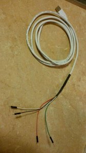
i made a programming cable for the USB connections so we can flash the boards when they get here

its very simple and inexpensive compared to commercial programmers

just take a USB cable, cut one end off

take male jumper cables, solder to the wires in the USB cable

apply tape or liquid electrical tape to the wires

use two sizes of heat shrink, one to do an initial cover, then one to overlap everything for added strength

it powered up a ZigBee development board so it works

RED = 5V VCC
GREEN = DATA +
WHITE = DATA -
BLACK = GROUND

Not bad for $13 and an hour of time

The boards will be flashed with software that allows WiFi updates, but to do the initial flashing, this tool will work

With a cable like this, if you accidentally erase the node completely, it is possible we can reflash it using this cable and TeamViewer without having to incur any delays for shipping - you can possibly do this your self from the secure site once its going if you have enough software experience

S605_LABEL#1_RED.png

programmer.jpg
 
Last edited by a moderator:
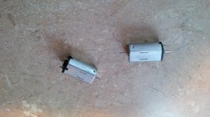
6V motors arrived, they start up with just 0.4 volts, will run up to 8V safely

they will work with boards 0001 and 0003, 0002 and 0004 are set up for normal 12V motors but the two latter will require constant track power as in existing DCC

IMG_20140806_130929.jpg

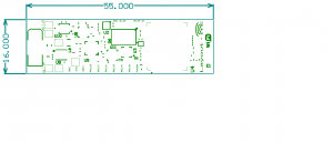
the silkscreen for markings on Loco-Node 0001 have been updated

0001_fixed.png
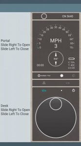
been working on a revised Android app with a layout demo as seen below. this application is being done in C# so its portable to Windows, iOS, and Android

UI.jpg

the last surface components needed by the assembly plant to run some of the pre-production boards arrived today, they are starting assembly

should have something next week to do the demo with

one set will then go out for certification

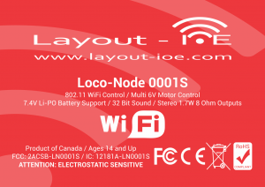
labels are in production

that's the latest update
 
Last edited by a moderator:
"one set will then go out for certification" - after they have been thoroughly tested to verify that no changes need to be made to the design or layout. :p

Hoping for the best.


Wow, cool beans! How is the testing going?

I soldered up a motor and about 40 LED's

Stuck in NYC until Tuesday

The boards went to Evan, he's getting one ready for a locomotive install.

Then he's shipping three to me.

There are 4 parts needed to go on each board when I get them, will send the parts to Evan plus a motor for his installation for his board when I get home. Then we can flash these boards and start power on tests. Then the board I have is going to Taiwan for radio, radiation, and EMI testing.

Waiting on a response from Juan, he normally doesn't respond until he's finished the task. We got the Wifi mesh working with the Node as indicated in the video I posted. The same framework is used to trigger other actions. We got sample PWM code for the motors a few days ago so the next update should show the motor working.

So baring any hardware defects in assembly, that locomotive will be running this time next week with the WiFi mesh using an HTC Android phone.

if everything is good, we have 100 PCB's that can be kitted and assembled with an email.

V1.2 of the design is ready if there is an issue, or any new refinements needed and a back up supplier of needed for the boards.

i sent graphics to Juan to start the front end before I left.

The video shows the back end only, you will not see this when operating the node.

in very good shape - will know more soon
 
Status
Not open for further replies.


Affiliate Disclosure: We may receive a commision from some of the links and ads shown on this website (Learn More Here)

Back
Top