Current and lights and things OH MY!!

ModelRailroadForums.com is a free Model Railroad Discussion Forum and photo gallery. We cover all scales and sizes of model railroads. Online since 2002, it's one of the oldest and largest model railroad forums on the web. Whether you're a master model railroader or just getting started, you'll find something of interest here.


Cee_Nnn

New Member
Here's one for those electrically / electronically inclined.

I recently purchased a set of HO gauge street lamps.
they came with instructions for a 16 volt supply and
separate 330 Ohm resistors for each pair of SMS lights

There are eight units of 2 lamps I wish to use five units, in one location,
and the remaining units in another. but I want to run them from a 5V source
They need not run very bright Just enough to be acknowledged as being "on",
say 10% of their capacity. I beleive they are 5050 SMS.

The question is:
Given the 5 volt source what would the appropriate resistance be for the two installations.
one of five sets and one of three sets? They would be wired in parallel, so if one lamp goes out
the others will still be lit. I'm looking for the specific resistor values, not a work around.
Appreciating your time in reading this.
Thanks
Cee Nnn
 
Do you have any specs? What voltage and current do the lights require. Some work at 12V. The math is very simple if you know the values. Resistance = (Voltage supply minus Voltage light)/Current light
 
I recently purchased a set of HO gauge street lamps.
they came with instructions for a 16 volt supply and
separate 330 Ohm resistors for each pair of SMS lights

There are eight units of 2 lamps I wish to use five units, in one location,
and the remaining units in another. but I want to run them from a 5V source
They need not run very bright Just enough to be acknowledged as being "on",
say 10% of their capacity. I believe they are 5050 SMS.
I think you mean SMD for Surface Mount Device, and the 5050 you refer to would be 5x5 mm, likely they are much smaller if they are in the street light itself.

Since LEDs one typically figures 20 mA current and you know there is a 330 resistor and a 16 volt supply voltage, we can use Ohms Law. Given one 330 ohm resistor and 20 mA of current the voltage consumed by the resistor would be 330 / 0.02 = 6.6 volts leaving 9.4 (16 - 6.6) for the two LEDs, so they are each consuming 4.7 volts, if in series as I suspect from the description. This seems kind of high for LEDs even white ones. If that is true your 5V supply will not be enough to light the LEDs.

I am suspicious about these numbers and the possibility that the two LEDs in the street light are in series. Can you supply a link to what you bought?
 
  • Like
Reactions: kjd


Thanks for the quick reply, KJD!
No, you have all the info I have. designed for 16v and R=330 ohms
I thought someone with a similar scenario might have an answer.
I know that with Ohms law having any two parameters, can give one the third.
E= I x R, I =E/R, R= I x E
I don't know the resistance needed or current draw. If I had that I'd have an answer...
Well, one close enough to start with...
LED's are not simple resistive devices. They have what's known as a voltage drop...
i.e. they use some of that voltage.
The current consumed, changes the circuit voltage. By how much, I just don't know.
That's what makes this difficult

Cee Nnn
Texas
 
I think you mean SMD for Surface Mount Device, and the 5050 you refer to would be 5x5 mm, likely they are much smaller if they are in the street light itself.

Since LEDs one typically figures 20 mA current and you know there is a 330 resistor and a 16 volt supply voltage, we can use Ohms Law. Given one 330 ohm resistor and 20 mA of current the voltage consumed by the resistor would be 330 / 0.02 = 6.6 volts leaving 9.4 (16 - 6.6) for the two LEDs, so they are each consuming 4.7 volts, if in series as I suspect from the description. This seems kind of high for LEDs even white ones. If that is true your 5V supply will not be enough to light the LEDs.

I am suspicious about these numbers and the possibility that the two LEDs in the street light are in series. Can you supply a link to what you bought?
Hello Jim,
Yes a typo. But they are NOT SMD's sfter all. Further investigation under magnification,
reveals them to be just small LED's . Their actual physical measurement is 3mm x 5 m.
There are no specifications on the site (a middleman for a European Co.) where purchased, they are just advertised as 3v HO scale lights, and the warning to not use them without the resistor( one 330 ohm resistor per two LED's and 16 VDC) . They are not wired in series though. Of that I am sure with 2 years college electronics under my belt ...( Wow 60 years ago!!!)...Too much water under the bridge!


Dbl lamp post.jpg
schematic.jpg

This is all they give as a schematic,..... and since I don't see a rectifier circuit ,
It appears to be a 16VDC supply. instructions say to connect the silver wires to the resistor,
so the resistor is common to both LED's . and there are four wires exiting the
Unit, only 2 of which are insulated

This is pretty straight forward for Parallel circuit They say light 1, light 2,
I call them unit 1 Unit two, as there are two "lamps" /Unit

Thanks for your time Also!

Cee Nnn
 
Last edited:
Some guess work on my part....... Lessee....
if they are truly 3v LED's and there are 2 of them connected to a common 330ohm resistor,

If V=IxR
therefore
R=V/I
substituting the numbers
R = 6 /.018

Then the math would be 330 / 6 = 0.018 Amps, or 18 milliamps half of which or 9 mA,
would be consumed by each lamp, then wouldn't a 9V Supply with a single 330ohm,
1/2W resistor work for 5 units?


OR DID I MISS SOMETHING??? (Right now I'm about brain dead....)
 
instructions say to connect the silver wires to the resistor,
so the resistor is common to both LED's . and there are four wires exiting the
The fact there are four wires tells me they are not connected together at all, a good thing and we believe each LED consumes 3 v (or probably close enough) and you have a 5 volt supply in your original post (I see in the latest you went to 9v) we can calculate the resistance for a given current.

While your math is correct your circuit thoughts are not quite. The two LEDs are connected in parallel through a common current limiting resistor. The voltage across the across the resistor will be supply voltage - LED forward voltage (of either since they are parallel) / 0.018 (18 mA) in your example. Since the LEDs are in parallel only 3 volts is consumed by both/either, but the current would be divided between the two equally since they are identical. Using your original supply voltage of 5v - 3v for the LED and having current through the resistor of 18 mA: (5 - 3) / 0.018 = 111.1, I would start with a 150 ohm resistor that would feed both of the LEDs at about 16.6 mA or 8.3 mA per LED which should be bright enough. Of course if it is not bright enough just use lower resistor values down to 100, 68, 56 and finally 47 ohms gets about 42 mA through the resistor or 21 mA per LED.

Here is how they would be wired with a common current limiting resistor, and the value for a 5 volt supply:
LED Streetlights.JPG

Note while the LEDs look red in the graphic the voltages used are the forward voltage for a white LED.

If you use your 9v supply and the supplied resistor of 330 ohms that is about 18 mA through the resistor and about 9 through each LED. And as with the 5v supply lower resistors will give you more current down to 150 ohms with 40 mA through the resistor and 20 mA for each LED.

For power rating that would be voltage across resistor times current (P = V * I). For the 5 volt supply with 150 ohm resistor: 2 volts consumed by resistor * 16.6 mA = 33.2 mW, so a 1/8 watt (125 mW) is all that is needed. For the 47 ohm at 42 mA, 84 mW, still 1/8 W. And the for the 9v supply 330 ohm with 6 volts at 18 mA is 108 mW, I would recommend a 1/4 W (250 mW) to keep the resistor from getting too warm. And for the 150 ohm with 6 volts at 40 mA is 240 mW, so you probably should go up to a 1/2 W in that case.
 
Some guess work on my part....... Lessee....
if they are truly 3v LED's and there are 2 of them connected to a common 330ohm resistor,

If V=IxR
therefore
R=V/I
substituting the numbers
R = 6 /.018

Then the math would be 330 / 6 = 0.018 Amps, or 18 milliamps half of which or 9 mA,
would be consumed by each lamp, then wouldn't a 9V Supply with a single 330ohm,
1/2W resistor work for 5 units?


OR DID I MISS SOMETHING??? (Right now I'm about brain dead....)

The fact there are four wires tells me they are not connected together at all, a good thing and we believe each LED consumes 3 v (or probably close enough) and you have a 5 volt supply in your original post (I see in the latest you went to 9v) we can calculate the resistance for a given current.
Agreed. The 9v example was just a test computation double checking my theory
While your math is correct your circuit thoughts are not quite. The two LEDs are connected in parallel through a common current limiting resistor. The voltage across the across the resistor will be supply voltage - LED forward voltage (of either since they are parallel) / 0.018 (18 mA) in your example. Since the LEDs are in parallel only 3 volts is consumed by both/either, but the current would be divided between the two equally since they are identical.
AHA !!!
Using your original supply voltage of 5v - 3v for the LED and having current through the resistor of 18 mA: (5 - 3) / 0.018 = 111.1, I would start with a 150 ohm resistor that would feed both of the LEDs at about 16.6 mA or 8.3 mA per LED which should be bright enough. Of course if it is not bright enough just use lower resistor values down to 100, 68, 56 and finally 47 ohms gets about 42 mA through the resistor or 21 mA per LED.

Here is how they would be wired with a common current limiting resistor, and the value for a 5 volt supply:
View attachment 215790
Note while the LEDs look red in the graphic the voltages used are the forward voltage for a white LED.
(Color understood)
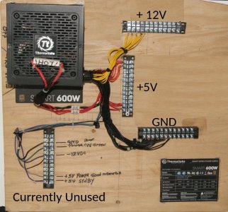
I have a 600 watt PC power supply that I have made a panel from.
PWR Supply.jpg
I'm using this along with Arduino, and DCC-EX for the layout .
that's where the 5 Volt refrence comes from.
Due to limited space, the layout is only 31 inches X 6 feet
Basically 3 ovals inside one another.
The lamp posts in question, are for a scratch built transverse eleveted highway


If you use your 9v supply and the supplied resistor of 330 ohms that is about 18 mA through the resistor and about 9 through each LED. And as with the 5v supply lower resistors will give you more current down to 150 ohms with 40 mA through the resistor and 20 mA for each LED.
Cool, but I won't be using 9V battery power but this may help someone else.
For power rating that would be voltage across resistor times current (P = V * I). For the 5 volt supply with 150 ohm resistor: 2 volts consumed by resistor * 16.6 mA = 33.2 mW, so a 1/8 watt (125 mW) is all that is needed. For the 47 ohm at 42 mA, 84 mW, still 1/8 W. And the for the 9v supply 330 ohm with 6 volts at 18 mA is 108 mW, I would recommend a 1/4 W (250 mW) to keep the resistor from getting too warm. And for the 150 ohm with 6 volts at 40 mA is 240 mW, so you probably should go up to a 1/2 W in that case.
FANTASTIC !!! Just the info I was looking for!!!
So again Jim, Thank you so much for your time and expertise.
Hope I can help someone one day!

Will post some photos when I get a chance
Cee Nnn
( aka: Charlie)
 
This is where those old DC power packs come in handy.
Hook up a street lamp, slowly raise voltage till you like the illumination. Measure the applied voltage.
 
Thanks Dennis.
In my younger days I would have thought of that.
lately though, I'm not as quick.
Here is a pic of one place I'm modelling for my layout.
It's in "Idar Oberstein" a little village in the Barvarian mountains,
about 60 miles Southwest of Mainz
It sits in a huge cave, about 300 feet above the town
Church in the rocks.jpg

In HO scale it stands about 2 feet above the table top and the church itself is
about 15 inches tall the windows are modelled with "Stained Glass" and it is lit from within.
I have a tunnel running under it. It is currently sitting on a shelf until the Layout is ready for it.
When I was stationed there in 1963 -1965 (US Army) it wasn't the pristine white, and
cream color you now see
It looked like an abandoned castle just dirty grey stone.
As I remember it.jpg


Then the area became noticed, sometime in the 1980's for it's Gemstones ,
and the church became a tourist attraction. It then, got the facelift.
and the roof of the cave, which dropped rocks on the town below, some a foot in diameter,
got cemented in place, as you can see comparing the old pic with the new.
there is an underground stream within the church, and you can get water from it.
I revisited it in 2003, 40 years after having served thereIt has changed sooo much!
there used to be a river, The Nahe that meandered thru the ttown...No More! They buried it in a tunnel
upon which a new (relatively) 4 lane highway was built. in the 80's.
But in keeping with the topic,
...............I can't wait to put the model, on my layout!


As promised Pics of the "Church in the Rocks" or "Kirchenstein", in German
Kirchenstein.jpg

As she sits high on the shelf. Has been gathering dust since 2022.
You can see my rail tunnel,under it, and I forgot I included the tower ruins at the top,
which dates from the 1500's. Church was built some say in late 1300's to mid 1500's.
And there is some folklore about 2 princes (brothers) fighting over the same girl, up by where the tower is
the one fell off the top during the fight, and the survivor as pennance, built the church where hie brothers body landed
As for the girl ? It's said she never married..... A touching tale, but full of holes. One person could not have done this work by hand in a lifetime. It would mean carting hundreds of tons of rock from the site, had he dug the opening in the mountain. and there is no trace of any rock pile that size anywhere near. and records show a sort of fort near the cave
a hundred or so years prior to it's build.
But I fell in love with the place and have included some semblance of it in my 3 previous room size model railroads.
The "Polaroids" of those, have long since faded...

Cee Nnn.
 
This is where those old DC power packs come in handy.
Hook up a street lamp, slowly raise voltage till you like the illumination. Measure the applied voltage.
Not for LEDs, since it is the current that you have to control not the voltage. I know most people think you are changing the voltage to the LED with the change in resistance, but in reality it is the current you are limiting. So an old variable DC power pack will not help with LEDs, the incandescent bulbs yes you could do this.


Affiliate Disclosure: We may receive a commision from some of the links and ads shown on this website (Learn More Here)

Back
Top