Control panel project (in progress)

ModelRailroadForums.com is a free Model Railroad Discussion Forum and photo gallery. We cover all scales and sizes of model railroads. Online since 2002, it's one of the oldest and largest model railroad forums on the web. Whether you're a master model railroader or just getting started, you'll find something of interest here.


tankist

Well-Known Member
EDIT 2/2011:
link to thread with ready product. below is the build timeline


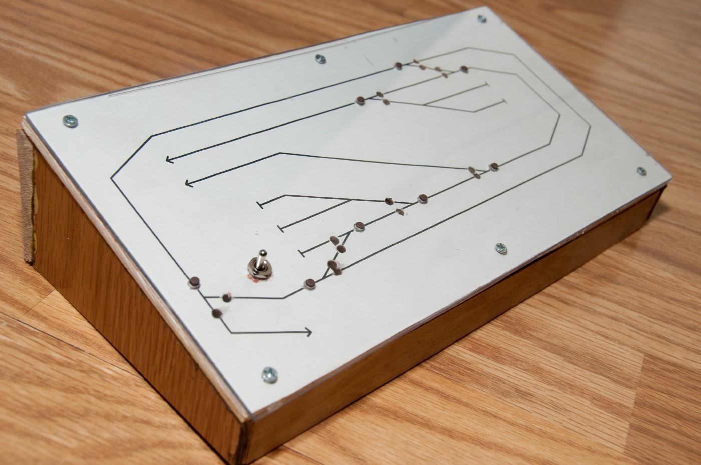
printed out layout diagram, glued it to piece of plywood and screwed sheet of plexiglas. drilled through holes for tactile micro buttons. i got the ones with longer shank so about millimeter is protruding. the holes for indication diodes are through plywood only.

and thats what i got
DSC_3313-vi.jpg


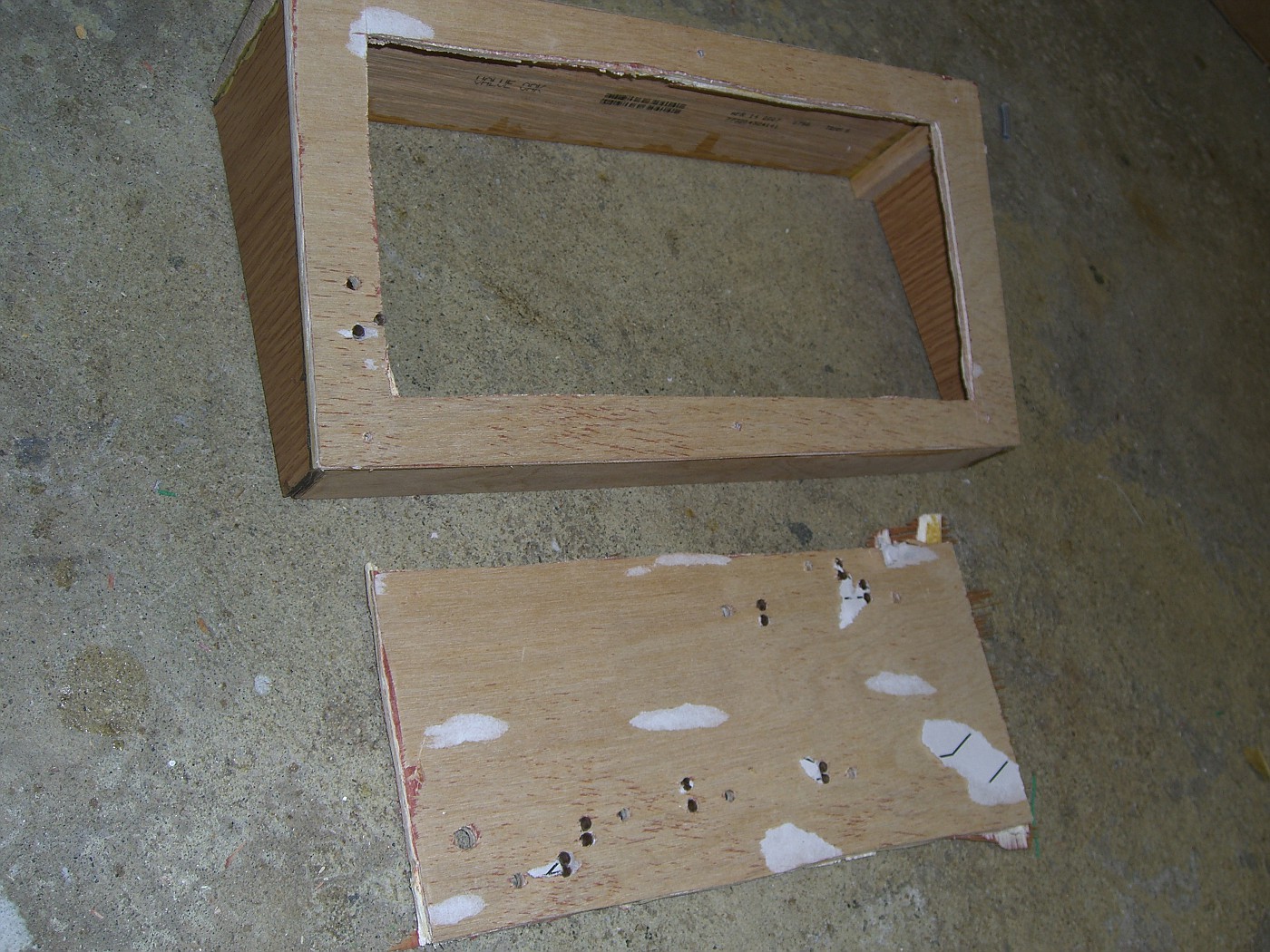
besides the fact it came out somewhat sloppy for my taste i realised that i decided to use pair of push buttons per turnout. yet again i hit my head with the same impatience stick :rolleyes: redesign was inevitable. i removed the top plexi cover and used it as back. cut another piece to size to serve as the new front cover. cut the middle plywood away leaving the borders for strength and as something to screw the panel to
CIMG1345-vi.jpg


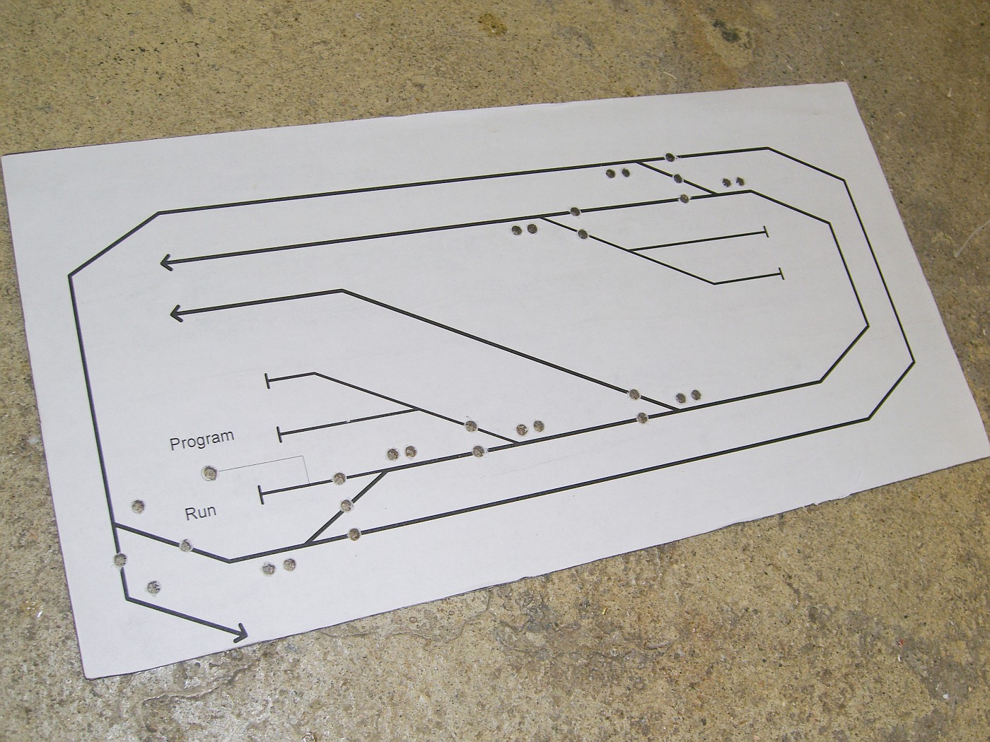
printed out new sheet with improved buttons and indicators layout. glued it to the plexi back and drilled 3mm holes for LEDs and pilot holes for the buttons.
CIMG1348-vi.jpg


lined up the two sheets, screwed them together and enlarged the pilot holes to fit the buttons.
looks cleaner now :)

CIMG1354-vi.jpg


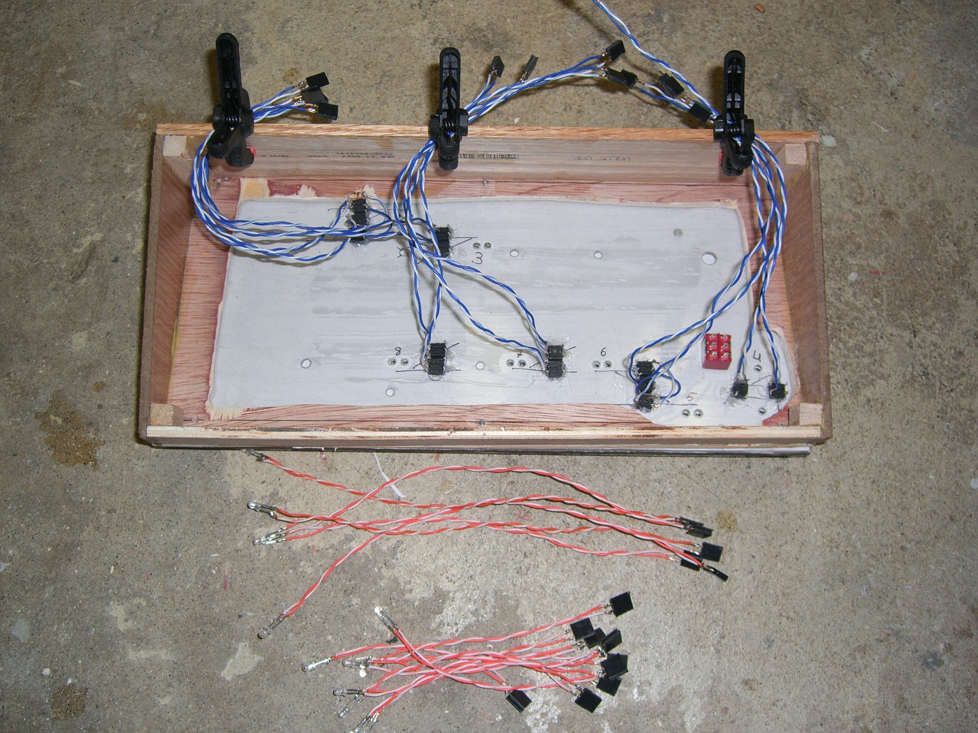
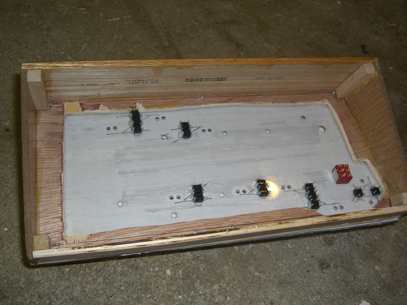
underside. marked the turnouts for less confusion during wiring. buttons are held in place with dabs of adhesive caulk. when dry it proved to hold them very nicely - took some effort to get them out of plywood. i will solder wire leads to LEDs before installing.
CIMG1358-vi.jpg


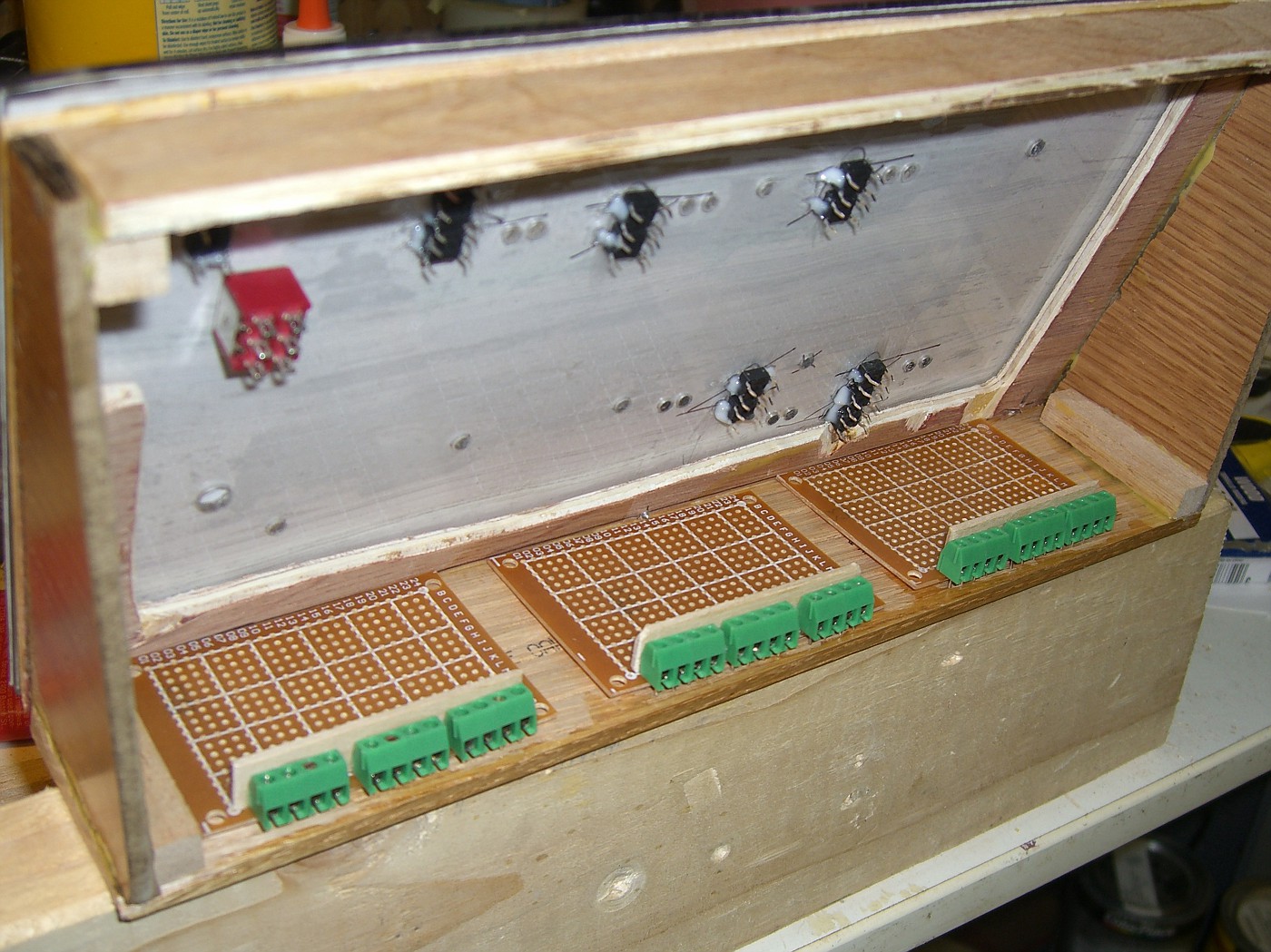
since there is some room inside the enclosure i will try to install the capacitor discharge units into it as well (blank proto PCBs shown)
CIMG1362-vi.jpg


and finally , thats how it will look when done :D
this time i'm quite happy with what i see

CIMG1361-vi.jpg
 
Last edited by a moderator:
It is a cleaner looking board. I can't wait to see the finished product or better yet more pics in progress. I enjoy seeing those.

Reid in NC
 
soldered leads with header connectors to buttons.
soldered wires to the LEDs as well. lucky me i decided to test them prior to gluing them in. i distinctly remember ordering bi color LED' in green/red. and what i got is Blue/ red :mad: WTF!!! what do i do with blue/red!?
EDIT: bunch of police cars perhaps, but chase scene from blues brothers is not something i'm going to model...

off shopping again and then desoldering the already wired LEDs :( ...

CIMG1367-vi.jpg


i guess i can use them as reds only...
if anyone wants blue/red let me know, i have a bunch of them
 
Last edited by a moderator:


great

hi tanklist,
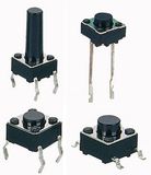
that is exactly the way i want me led's to work..i have attached a pix of the momentary switches i use..i use 2/turnout whereas it seems u only use one per turnout..is it the same switch i use or is yours much different? i can see ur led's are they the bezel type?
i can see some of the wiring but nothing as yet to the led's..looking at the underside of ur control panel i can see the bottom of the switches...never seen that type before what are they? ON/OFF switches? have you finished the wiring up of the control panel yet?..if so how but some pix of it...showing the led setup....
 
i will be tapping into DCC line (that is going to the run/program toggle) for power to light LEDs. i read that to rectify high frequency signal such as DCC fast switching diodes are needed so i ordered bunch of schottky diodes. got them today. after the schotkky bridge, voltage will be regulated with 7805 for at least some DC compatibility.


kato.

the switches are simple SPST miro buttons with long shank. they also call them tactile buttons. the button you posted is more expensive (when you need 16 of them it adds up) and frankly i don't really like how it looks mounted.
Tact-Switch-Plug-In-.jpg


i wanted to use 1 momentary button per turnout but that would require some sort of latch (probably SR or other flip flop based) to pulse one side then the other. i don't have enough skill to design such circuit so i took the shortcut. as you can see on the latest pics i do have 2 buttons per turnout - one selecting thrown, one through routes.

below is the capacitor discharge circuit i'm building (featuring charge current block and 'ready' indicator LED). i really like the idea of relegating the actual switching to semiconductor components. this way there is no chance button will stick and burn out coils. this one is is taken from here: http://home.cogeco.ca/~rpaisley4/CircuitIndex.html

CDDAR.GIF


as for indication i installed pair of micro switches on each turnout (see pic below) effectively creating a DPDT. they are independent from the CDU circuit. meaning if i to manually throw the turnout i will still get correct indication.
no pics showing led setup yet. as i said yesterday, i received wrong color LEDs. and it is about 10 days till the correct ones will be here (ordering from ebay. china...)
i'll keep posting the progress as it happens.

DSC_8919-vi.jpg
 
Last edited by a moderator:
Looking Good Anton! I'll need a panel for my hidden track so I'll be watching... ;)
If I need red/blue LED's I know where to go.
How did you mount the micro switches onto the machine, great idea!
 
How did you mount the micro switches onto the machine, great idea!
if this is a statement - thank you :)
if this is a question - i super glued the micro switches.
it is just insane they ask ~10$ for PL-15 accessory when the micro-switches are 30 cents...
 
soldered new LEDs to lead wires flattened the dome and glued them into the panel. everything looks the same apart that there are twice as much wires sticking from the underside now. a jungle...

CIMG1393-vi.jpg


started on the boards these LEDs plug in to.


i went through that bag of chinese diodes and tested every single one. about 80% were blue/red. the rest were actually green/red and there were coupe of 3 legged ones. lucky me to get an odd bag.
 
Last edited by a moderator:
Your control panel face is looking good. For the control panel face, I use sheet PVC (not foam core) and get it from sign shops. I haven't worked with plexiglass.

How is the progress of your circuit from Rob Paisley? I would like to find someone to build one of his other circuits - http://home.cogeco.ca/~rpaisley4/xBellRinger.html - do you know of anyone that might be interested? I've done some LED and switch wiring but am not very successful with electronics.

Regards,
Jon
http://www.dollhousedesigns.com/ModelRR/ModelRR.html
 
Hey , John
thanks!

as for CDU i built Rob's circuit and surprisingly works. surprisingly since its me who built it, lol (see the link to CDU thread in my sig).

that looks like a very simple circuit and i actually have all the parts needed for it including terminals. Correction - will need to order the 555IC.
you can expect similar quality to my circuit (which i guess is questionable but it works). however i don't have the bell pictured so the only test i'll be able to do is output to ordinary relay. let me know if interested
 
Last edited by a moderator:


Anton -

The control panel looks great!

Where do you purchase your plexiglas, and what tools and techniques do you use to cut it to size?

Thanks - Jeff
 
Hi Jeff, thank you )

that sheet i purchased in menards. not the best or cheapest place really.
cutting it to size was simply cutting it in half. to cut i scored deep groove in it with a sharp screwdiver (since i didn't have the correct blades for the knife) and broke it along the line.


Affiliate Disclosure: We may receive a commision from some of the links and ads shown on this website (Learn More Here)

Back
Top