ModelRailroadForums.com is a free
Model Railroad Discussion Forum and
photo gallery. We cover all scales and sizes of model railroads. Online since 2002, it's one of the oldest and largest model railroad forums on the web. Whether you're a master model railroader or just getting started, you'll find something of interest here.
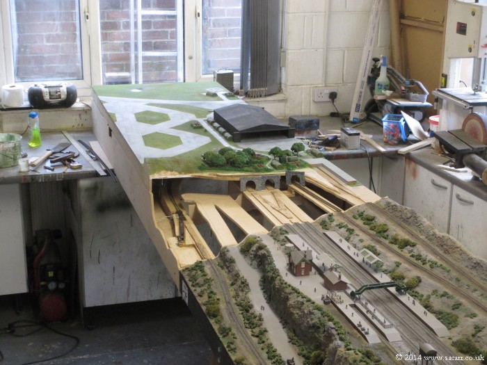
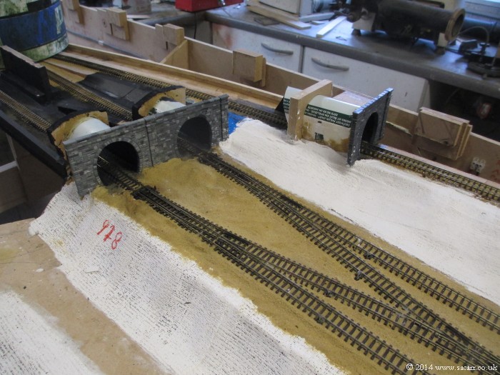
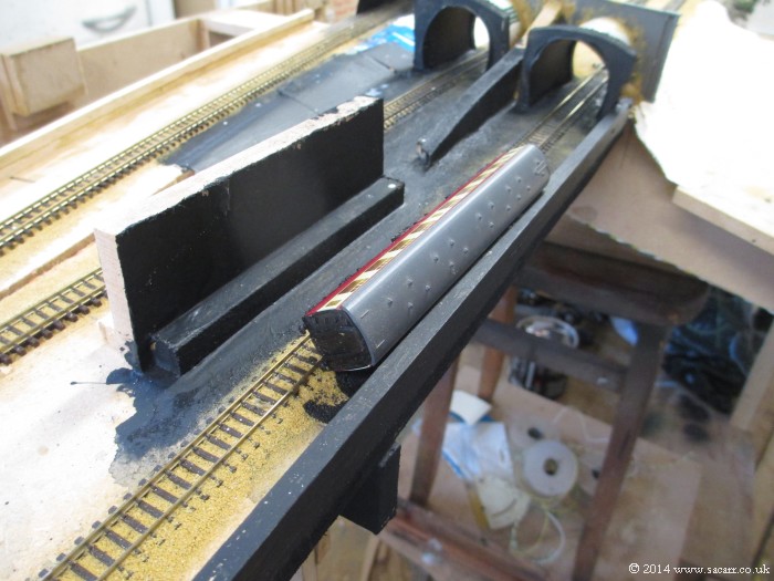
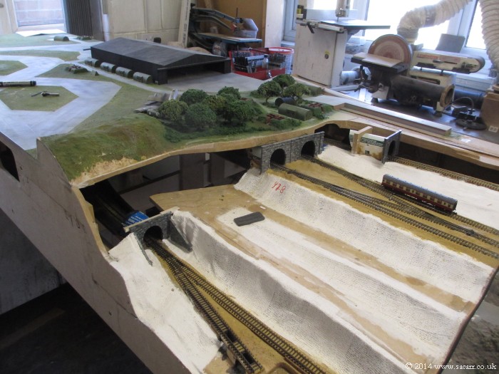
A closer view shows the tracks running into the hillside. I'll need to lower the track bed slightly on the climb up to the airfield to give a bit more clearance under the airfield top.
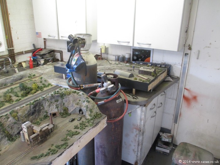
I did a quick measure of the workshop and layout this morning and there should be just enough room to fit the mine section on the end once that is built. This means that I will be able to connect all three sections together, forming a complete dual track loop for testing.
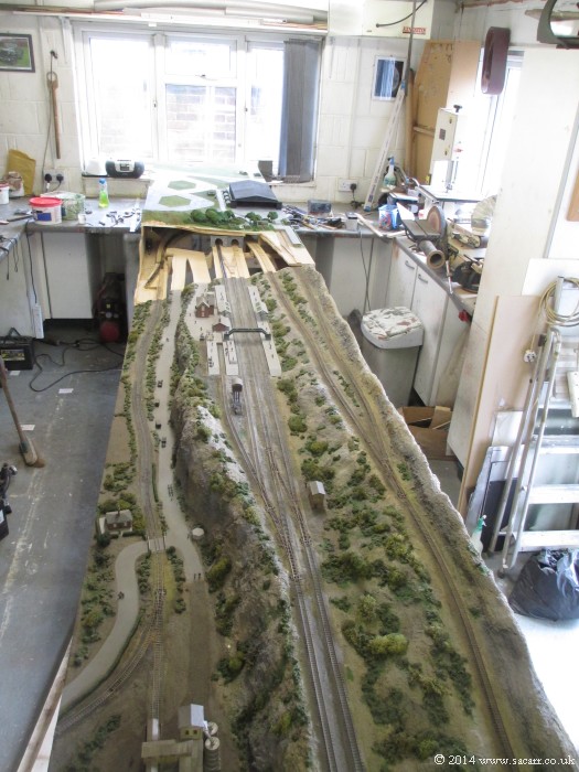
A view along the main lines again.
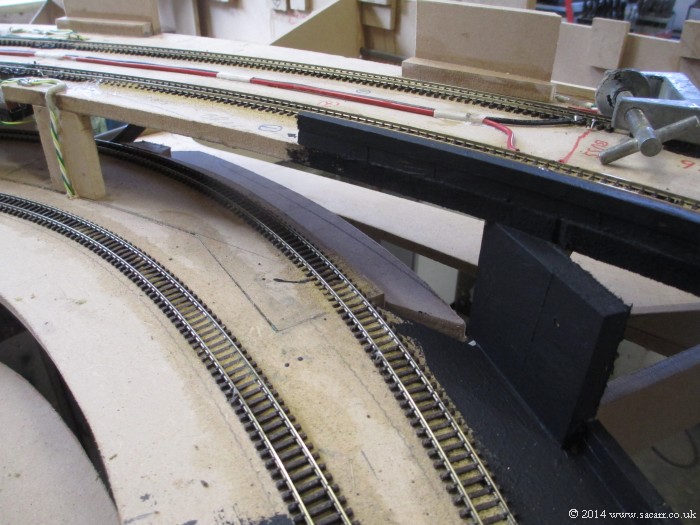
This is where the tracks curve out of the airfield section side, towards the next section. I may cut some additional inspection windows in the front face of this section to allow monitoring of trains within the tunnels.
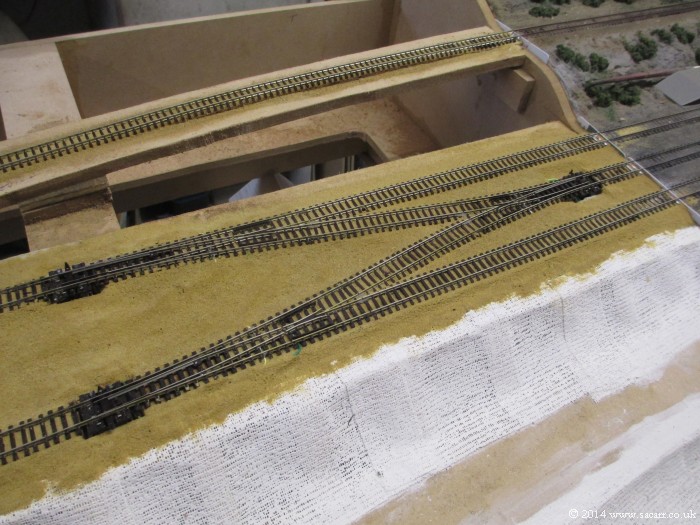
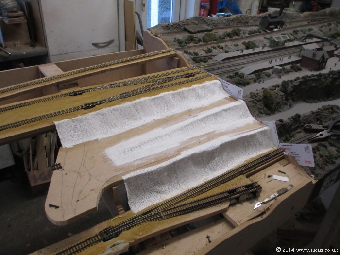
Once all the track was laid, all the visible areas were ballasted, plus a few stretches that were hidden in order to help hold the track in place. The 'Modroc' substructure was also added to the hillside around the road.
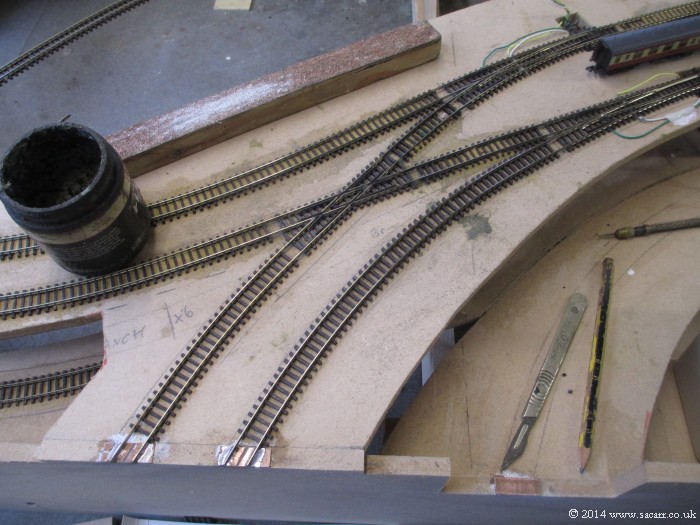
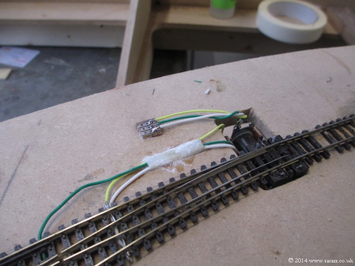
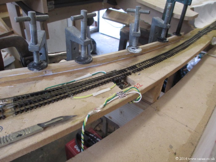
The tracks that lead off the board are secured at the ends by copper clad board, glued down with the rails soldered to them. The point solenoid wiring is also attached to copper clad board, to allow easy wiring to the decoder later.
At the back of the layout, the tracks exit the boards at a very shallow angle. I didn't think I would be able to get a good alignment of the rails in the usual manner, especially as they would have to be finely tapered. Instead, I stopped the tracks short of the board, leaving a short length of rail overhanging the copper board, to allow a rail joiner to be fitted. A short length of track will be cut to bridge the gap onto the rear section.
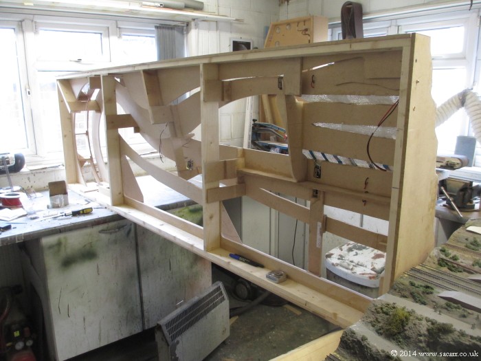
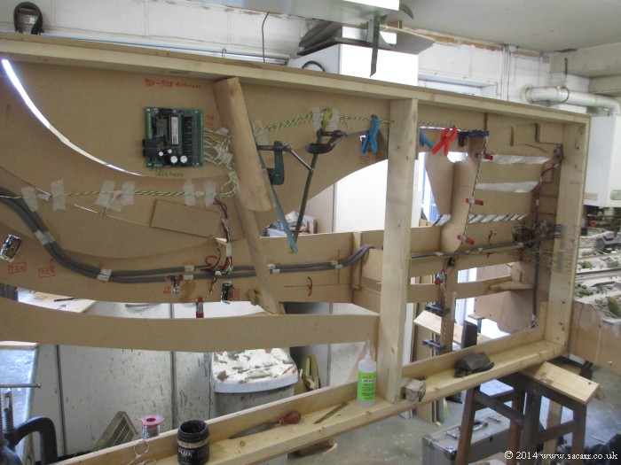
It was time for wiring next, and the section was tipped on its back to allow the cables to be run below.
Connections were mirrored from the previous board onto the airfield section. Loops of wire will connect them using screwed terminal blocks. The ring main for track power was added next, with fly leads off to the various sections of track.
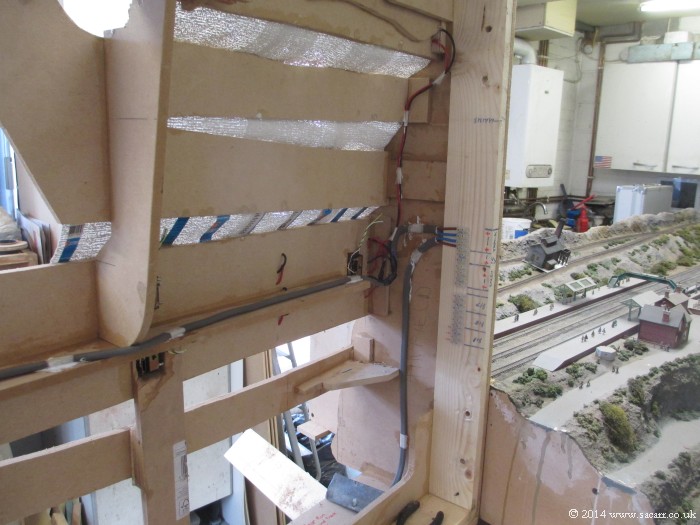
Here's a close up of the terminals. Three points are controlled by a decoder on the previous section. The wire I've used for these is quite fine, so I've added some thick copper wire into the screw terminals, and the thin wires are soldered to these. Each set of wires has the decoder address added to make following the wiring easy.
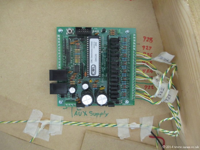
The DAC20 decoder was screwed to the bottom of the layout and that allowed the points wiring to start. Each decoder output was labelled with the address, as was each point motor, according to a pre-designed diagram. Masking tape was wrapped tight around each cable to allow it to be glued in place, and further strips held it while the glue dried.
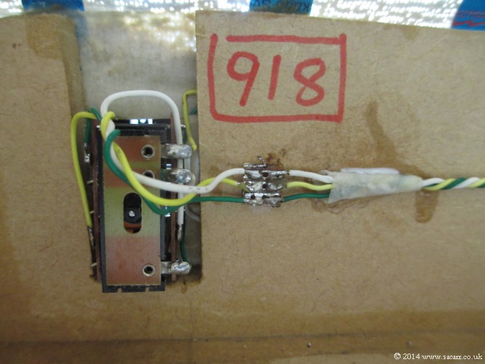
At the other end of the wire, they were soldered to the copper clad pads by each point.
A combination of tape and clamps hold wiring in place while the glue dries in this shot. Much of the wiring is complete, although the terminals still need to be added where the tracks curve off the other end of the board.
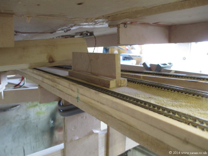
Back on the top of the section, small wooden walls were built where tracks run close to the edge, to prevent derailments from falling from the layout. This is the lower branch line.
Along the edge of the side panels, several small alignment plates were glued in place. These allow the airfield top to slot into place and align accurately on the lower section.
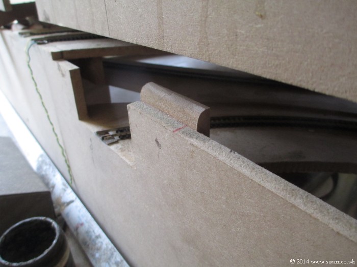
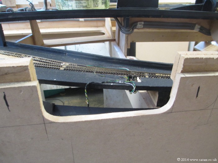
On the upper branch line, the bottom of the airfield board was carved out a little more, to give more height clearance. One small section of the airfield lighting wiring also needed to be recessed into the board, to make sure it didn't interfere with trains running so close below it.
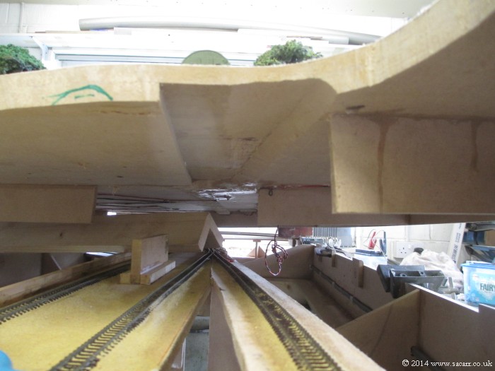
This support for the airfield was added between the two main lines. Because of the need to cut out some of the original airfield structure to clear the tracks, it was allowing the airfield surface to sag by about 1/4 inch, reducing track clearance height. This support and a number of others, yet to be added, will bring it back to level and help to tie the two layers together.
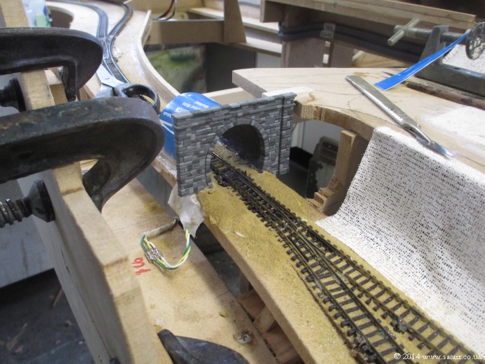
I then began to fit the branch line tunnel mouth.
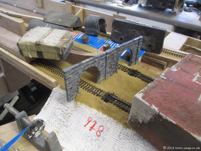
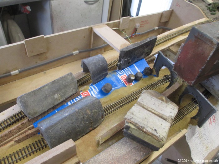
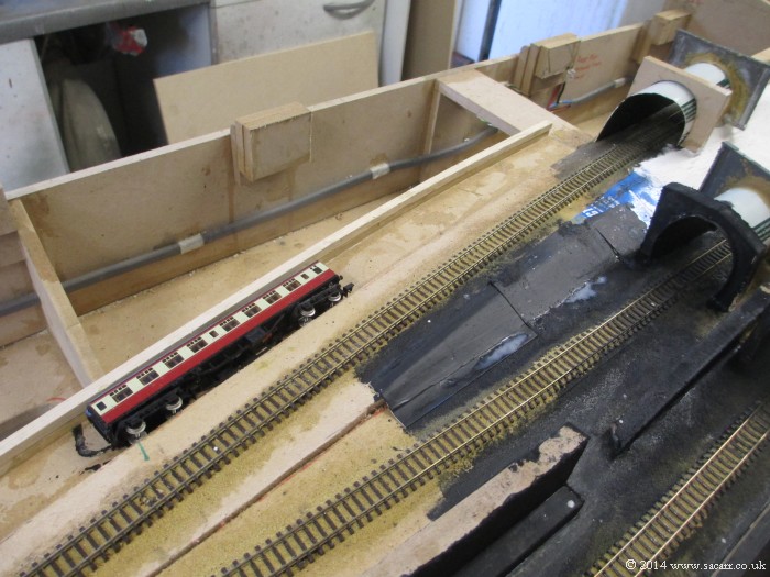
The main line tunnels came next, with a wooden support glued behind to hold them vertical. Several lead weights hold everything down. The gap between the upper branch line and main lines, was filled with card to prevent derailed trains falling through the gap. Outside of the tunnel, the landscape does that job, but under the airfield, there are several areas where precautions need to be taken.
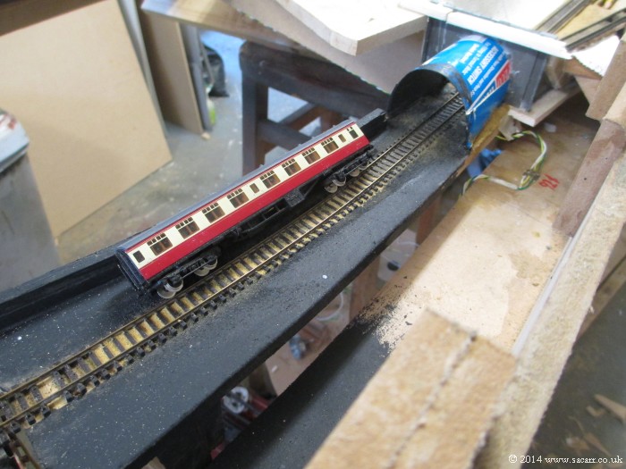
A short length of card was formed into the inside of the tunnel. I didn't make them very long as access for derailments it limited at the best of times. A small MDF former holds the rear of the card tube. The board inside the tunnels was also painted black to help darken the area.
The lower branch line tunnel has settled into its cutting now. So that the road from the quayside has somewhere other than the station to go to, I'm going to add a bridge leading it off the edge of the layout.
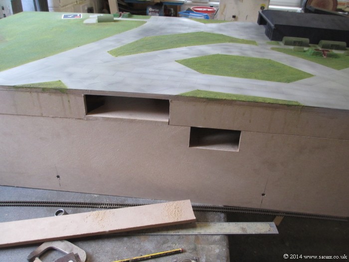
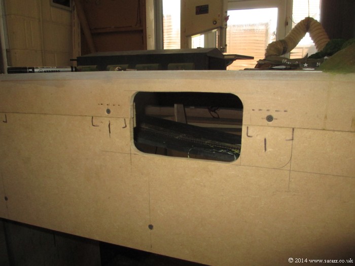
In the front of the layout, overlooking the branch line shortly after it enters the tunnel, I've cut an inspection opening to allow checking for derailments.
On the upper branch line, I've also added a derailment catcher.
The main line catcher in action.....
.....and the same on the lower branch line.
Here's the start of another branch line catcher, under the main line. This should be the last one needed.
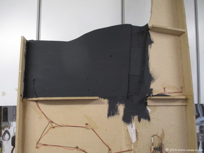
The bottom of the airfield was painted black in the area of the tunnels to further darken these areas.
No updates for a while, but I've still been busy. On June 10th, I made a test rig for the smoke system. The smoke unit will have to be located below the airfield surface, but away from the position where the smoke will exit. This is due to the fact that the best aesthetic position for the Lancaster also falls directly over the main line, and there isn't much height clearance.
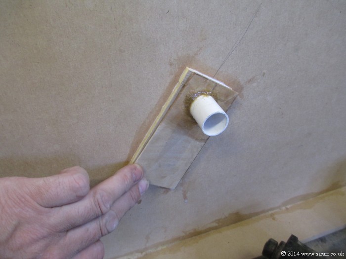
So using some scrap wood, I hollowed out a channel in what would be the airfield base, gradually widening from the point of the smoke generator. A small shallow box was built over this, to give a reasonably sized chamber for the smoke to expand into. At the opposite end of the box to the exit hole, I glued a 22mm plastic pipe to funnel the smoke into the box. The removable smoke generator would be filled, then inserted into this tube, so that all smoke produced would be contained, and as the warm smoke rises, fresh air can flow up past the generator, allowing a through flow of air.
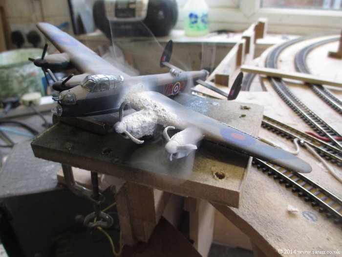
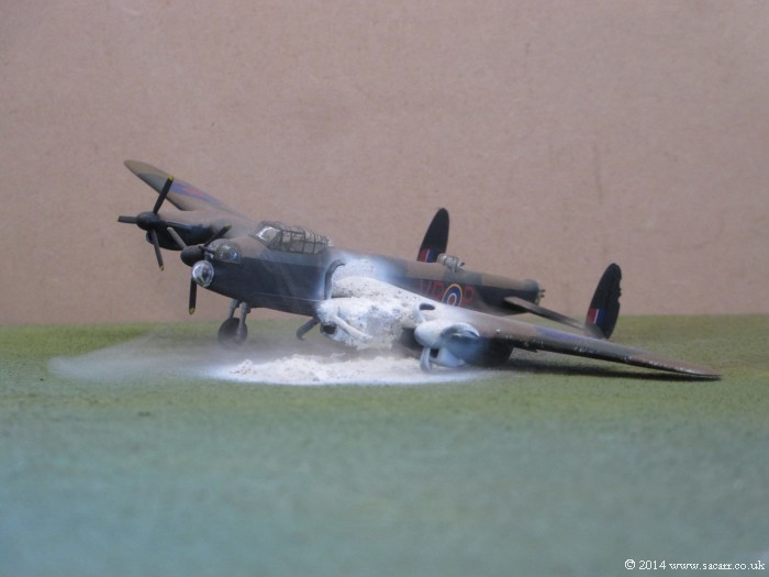
This picture shows the Lancaster on the test piece, with the smoke system switched on.
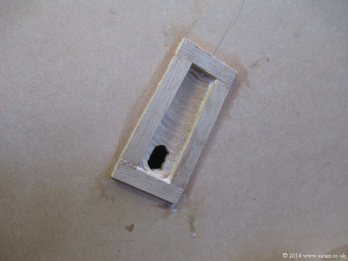
Once I was happy that it was working, I then repeated the construction on the base of the airfield section. This is the hollowed out base board, with some 4mm ply edging to create the smoke box.
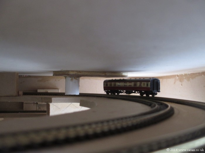
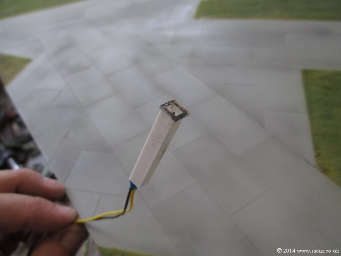
On top of the smoke chamber, I glued a 1/16 ply face with the plastic inlet pipe. The total height was about 1/4 inch, and this gives just enough clearance for the trains to pass below it; but only just!
The smoke generator is a Seuthe unit from Gaugemaster. I've bought a small timer to control the smoke, so that it automatically switches off after a pre-set number of minutes.
Here's a picture of the Lanc resting in place with the smoke operating and also a video of the first test. The scene should really come to life once the crash vehicles, fire crew and other figures have been added.
[video=youtube;w6-r4qLc02w]https://www.youtube.com/watch?v=w6-r4qLc02w[/video]
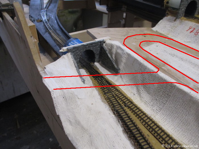
With the smoke system sorted, the airfield top could be fastened to the base. The top was going to be glued, but that will guarantee a track failure, so I'm making it removable; though with a bit of cutting needed. The basic airfield board will be screwed in place, but the hillside that joins the lower section to the airfield would need to be cut for removal.
The airfield is screwed in place here, ready for the hillside work to begin.
The inspection hole was opened up too, giving a pretty good look at most of the trackwork.
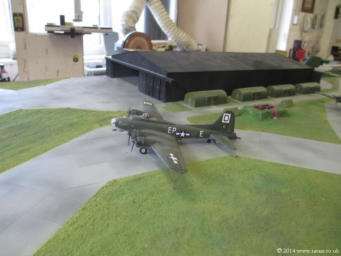
The B-17 with the operating engines was fitted next, and the wires routed down through the board to a clear space below where they can be accessed later.
Out came the styrene next, to extend the road, and then the plaster bandage and building plaster to create the hill.

Affiliate Disclosure: We may receive a commision from some of the links and ads shown on this website
(Learn More Here)