ModelRailroadForums.com is a free
Model Railroad Discussion Forum and
photo gallery. We cover all scales and sizes of model railroads. Online since 2002, it's one of the oldest and largest model railroad forums on the web. Whether you're a master model railroader or just getting started, you'll find something of interest here.
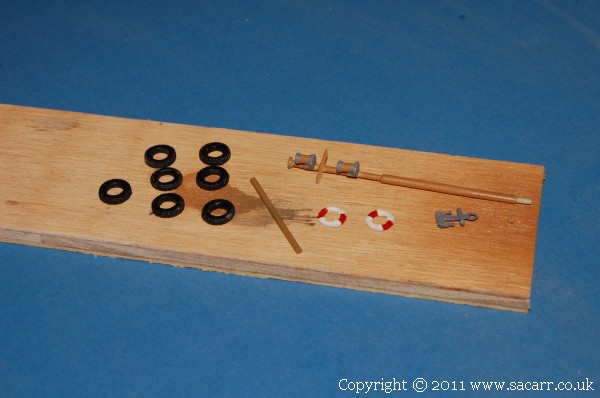
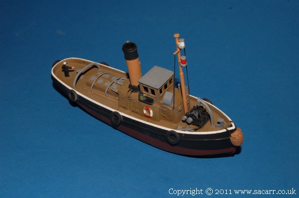
Here's the tyres and other small accessories left to fit the tug, pictured at the end of the day.
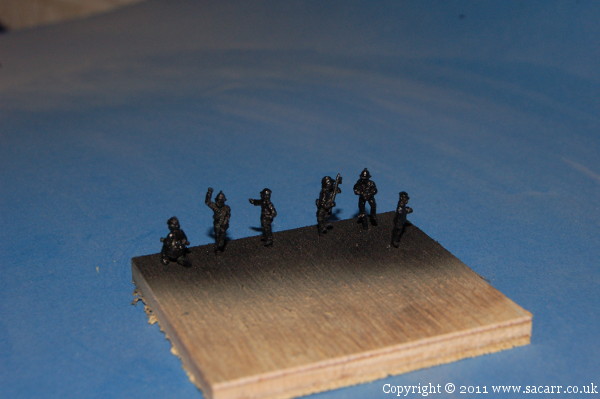
Also painted were the firemen. They still need their detail painting done.
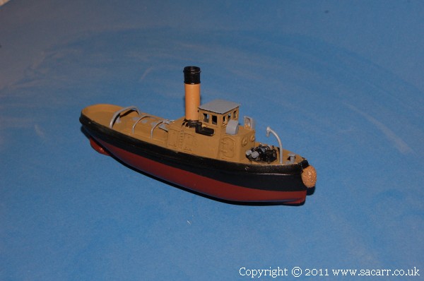
The deck and wheelhouse were brush painted brown, actually a darker shade than the flash makes it appear. Other details were also brush painted. A captain was added to the wheelhouse, but due to his height and a low ceiling, I had to grind a hollow into the inside of the wheelhouse roof to give his head the clearance it needed.
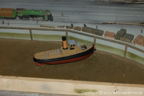
and on the layout in the approximate location it will go.
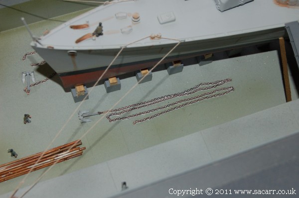
I found some suitable chain for the anchors, though not a huge length. This was sprayed a more appropriate colour. One length was cut into 15 fathom lengths to represent the chain separated at the shackles. The other was left as a continuous length. They were glued down with thinned white wood glue and will receive a matt coat once fully dry.
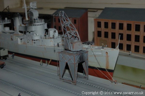
The tracks for the new crane were sealed down with a clear matt coat and left to dry. The cranes were then weathered and the new crane was glued down.
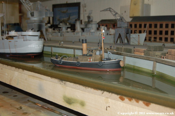
The tug finally finished. This involved further detail painting of lights and other small parts. The top edge of the bulwark was painted white. Mast, rigging, anchor and tyres fitted, and a matt coat. One of the firemen was given a white hat, and he became a crewman on deck.
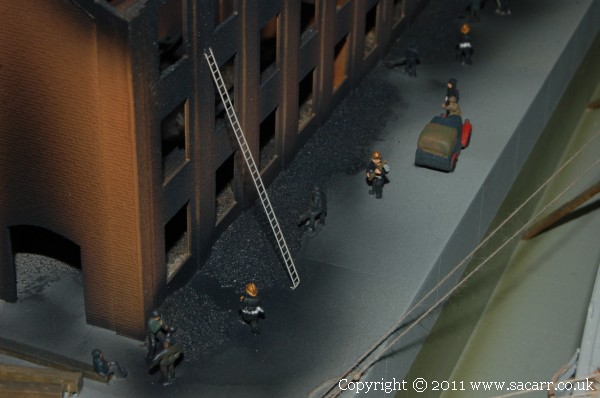
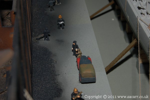
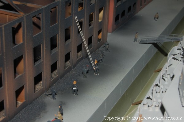
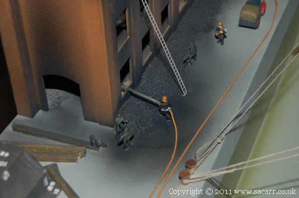
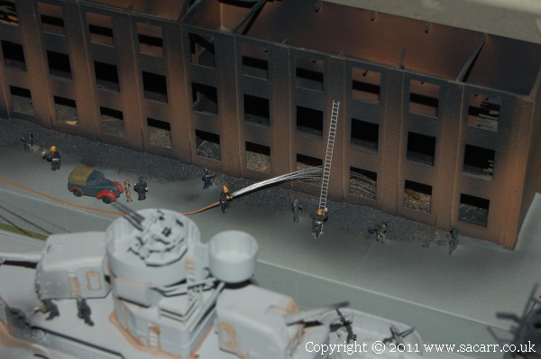
The firemen had all their detail painting finished and were attached to the layout. The white metal figures were quite easy to attach, as each figure had a thin metal sprue extending from one leg. All I needed to do was drill a hole in the base, add a little glue and push the metal pin in the hole. A couple of firemen are holding hoses which will be connected to the fire truck once it arrives.
The fire chief is talking to the bomb disposal officer.
Two ladders were also added where the firemen have been checking the structural integrity of the building following the fire.
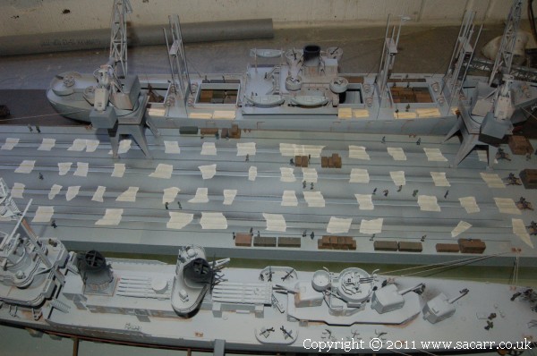
I decided to make a start on the concrete between the tracks. Having cut a few trial pieces of styrene of different widths, I settled on a strip 6.5mm wide which would sit on the sleepers between the chairs. This gives about 1.25mm clearance for the wheel flanges.
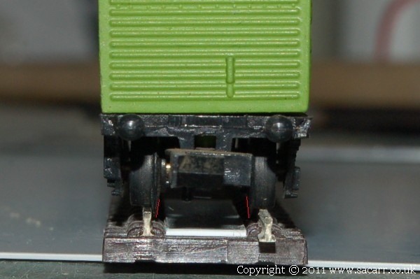
I would have liked less gap, but I didn't want to take any chances on interference with the wheels. At a larger scale, it would be possible and because of the scale would look smaller. This wagon shot highlights the wheel flanges in relation to the concrete strip.
Here's the first strip glued in and held with tape. These strips of concrete still need blackening with the airbrush as can be seen on the outsides of the rails. This is to simulate the coal dust and ash from the locomotives using the yard.
I got all the straight sections added which were left to dry. Trimming the plastic for the curves and points will take some time!
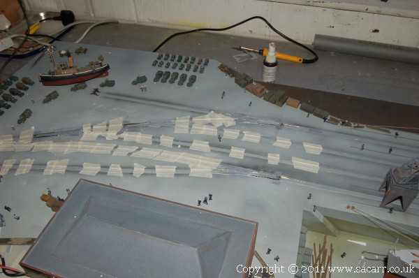
The concreting is done, bar some slight sanding and filling here and there. For the gentle curves, the 6.5mm strip of plastic would bend to follow the curve. For those that were tighter, the styrene was cut into shorter sections. These were all taped down to dry.

I pondered over the points for some time, tried trimming styrene to fit around the frog and check rails and realised I was going to be there forever doing it that way. I settled on Milliput epoxy putty to fill the majority of the point. It was mixed and squeezed and moulded around the rails, and then a flange gap was made by pressing a piece of thin styrene into the putty. After it had cured for a while, but before full cure, the flange gaps were cleaned up with a scalpel and then wet and dry rubbed along the slot. A very thin piece of styrene, probably 0.25mm, was cut and glued to the switching rails to fill that area. The holes where the tie bar is were covered with 'access panels' to allow the railway maintenance crews to access the point controls.
They were given a quick coat of grey just to make it more easy to see what needs filling as the white Milliput doesn't show imperfections that well. There were still some gaps in the points. I don't feel comfortable putting any more glue and filler in there for fear of either gluing the point solid or increasing the chances of derailments. As mentioned before, at a larger scale, closing up the gaps could be more effective, but with N, you have to make compromises.
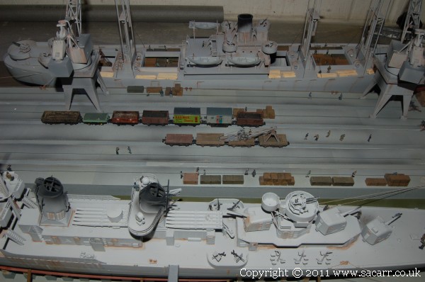
The rest of the quayside had the tape removed. These sections of concrete still need weathering and a matt coat to dull them down, but the overall effect is quite good now.
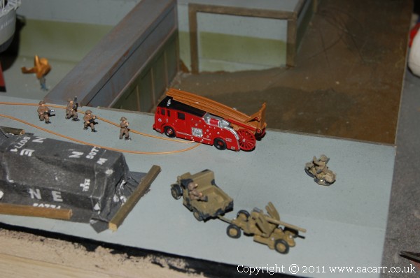
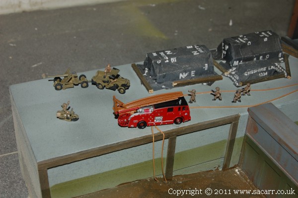
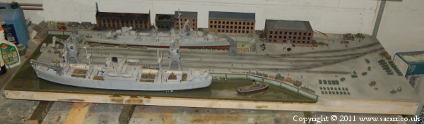
Another parcel from the postman brought some more goodies for the railway! Try as I might, I couldn't find a 1940's fire engine, so this 1950's model had to do. I tried a number of different places for the fire engine, but with the Morris truck towing the bofors gun, it would have blocked the route the Morris would have just driven along. The only option was to move the Morris and Bofors to make way for the fire engine.
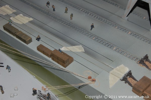
Canvas fire hoses were made from thin copper wire sprayed, and glued down. One end passes from the water in the dock to the fire truck, then from the other side of the fire truck to the two firemen.
I couldn't have the firemen standing there with the hose doing nothing, so they needed water; but what to make it from????
After much pondering, I remembered about some fine Fibre Optic cable I had, gathered a small bundle, and super glued one set of ends together. The other ends were allowed to splay out. The glued end was then glued to the end of the firemans hose. I think they look pretty good!
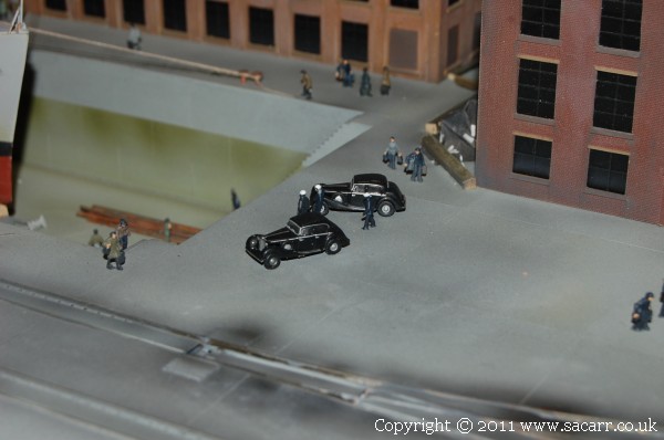
Other vehicles added were two Navy staff cars which have just arrived on the scene. Three officers survey the repairs on the Destroyer.
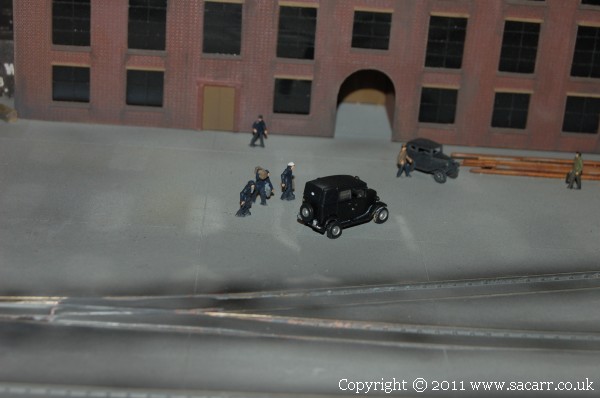
Heading the other way are three sailors walking to a taxi; off on leave or posted elsewhere. They were probably part of the Destroyers handover crew, and amongst the last to leave.
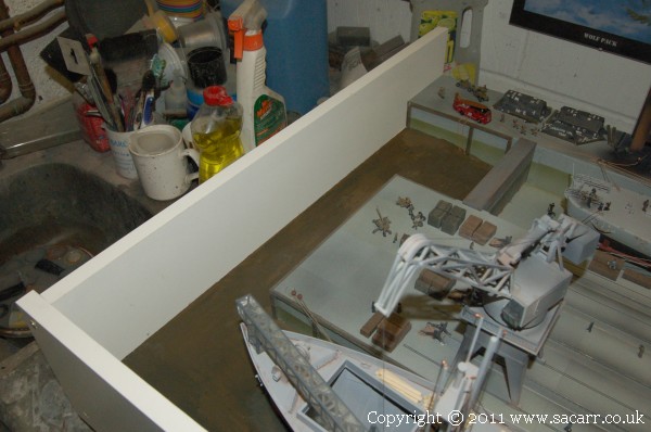
Mid April - I started out with a shopping trip to B&Q, followed by a big tidy up of my painting bench so I could move the quayside to the other end of the workshop, leaving my building bench free. The B&Q trip was mainly for some Conti board to make a dam around the area of water. The board was drilled for screws to hold it to the sides of the quayside section, then waxed with mould release wax to prevent the resin from sticking to it ( hopefully!!!! ). The board was then screwed to the side and end of the quay.
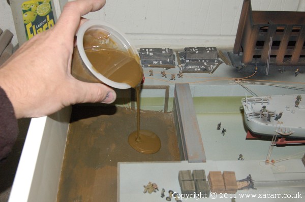
While there are a number of cheap polyester resins that can be used for water, I was concerned about the styrene dissolved in the resin attacking the hull of the Liberty Ship. As a result, I had to go for the more expensive epoxy resin. This was to be poured in several layers, with the bottom layers having quite a bit of brown paint mixed in to hide the baseboard. Here we go, the first pour.
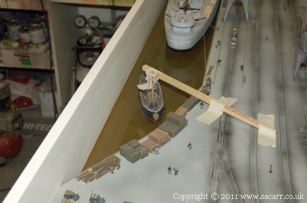
The tug was held upright with a wooden support taped to the quay.
Once the first stage of the resin was poured, I made a start of section 2!! The epoxy takes 24 hours to cure, but I wanted to pour the next layer before full cure to get a good chemical bond between the two layers.
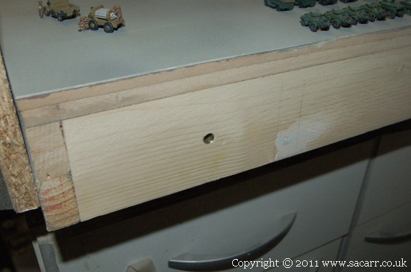
So, the next section. The first job was to sort out the alignment of the frames on the two sections. Some time ago, I bought some cabinet makers dowels to align the boards. The section of 3x1 timber, which is the supporting frame of the second board, was clamped to the end of the quay section and carefully aligned to the correct position. Two points were then marked out and drilled for the joining dowels, which were then hammered into the frame. While still clamped, a third hole was drilled for the bolt which will clamp the sections together. The first photo shows the female dowel in the end of the quayside section.
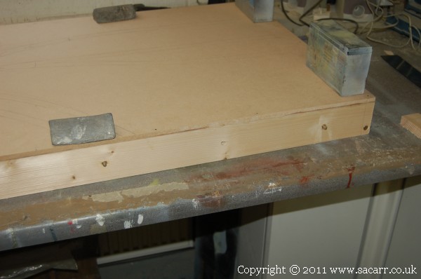
Picture two shows the male dowels sticking out of the frame of section two; the quayside yard.
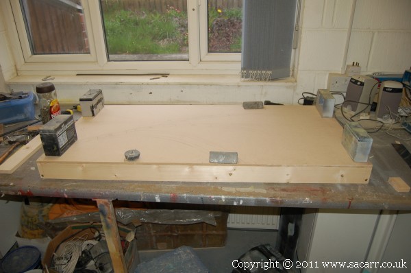
Real progress, the second section is now framed up!
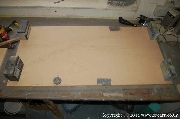
On this overhead view, you can just make out the track plan drawn out on the base board. Another model shop visit is on the cards to buy or order the next set of points and motors.
Around mid evening, after the first layers had cured enough to be firm, the water had another layer of resin applied.
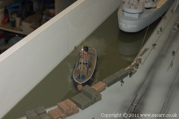
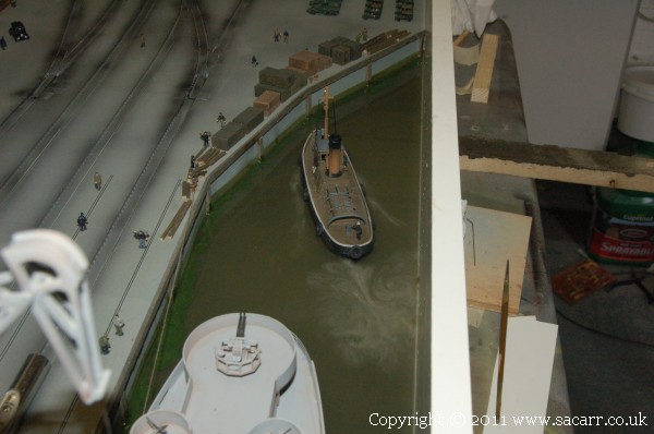
The last of the water was poured on 16th April. There was only 250gms left, so it only forms a thin layer, but enough to add the final detail to the surface. After the majority had been poured in and spread around, I mixed in some fibre glass 'Micro Fibres' into the resin that was left. This thickened up up a little, and gave it more of a white colour.
A tiny bit of brown paint was added to take the edge off the white and it was carefully poured in behind the tug and landing craft. With the handle end of a paint brush, I dragged the white mix and swirled it into the clear resin, creating the froth generated by the props of both vessels. I'm quite pleased with the result.
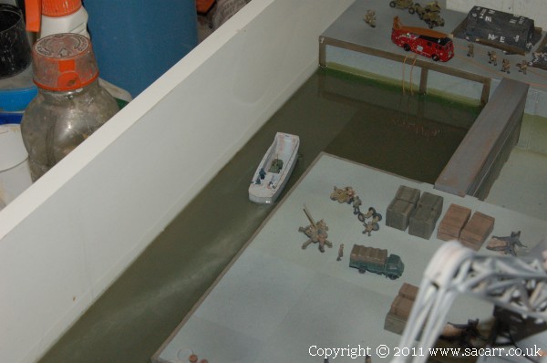
Here's the landing craft which was placed into the last wet coat of resin since it was a flat bottomed model. This still needs a few troops gluing in.
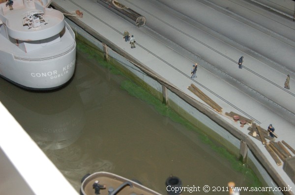
The very last of the resin had some green paint mixed in, and this was applied around the edge of the quay as weeds.
The following day was warm, so by late afternoon, the resin had cured enough to remove the Conti boards. Doesn't look too bad!
The crane instrument panel was painted, followed by adding the lettering for the controls. The three switches on the right that select left or right crane were linked with a joining bar and a master switch was added so the cranes only need to be powered up when being used. The rest of the time they can be switched off to save wear and load on the servos.

Affiliate Disclosure: We may receive a commision from some of the links and ads shown on this website
(Learn More Here)