ModelRailroadForums.com is a free
Model Railroad Discussion Forum and
photo gallery. We cover all scales and sizes of model railroads. Online since 2002, it's one of the oldest and largest model railroad forums on the web. Whether you're a master model railroader or just getting started, you'll find something of interest here.
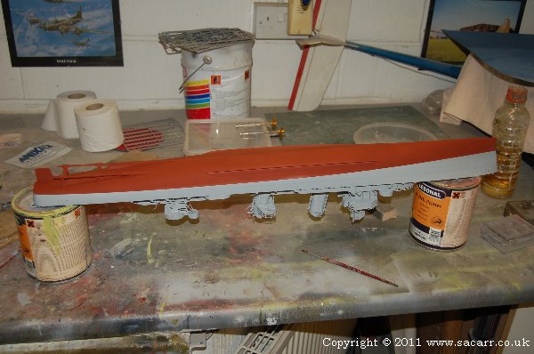
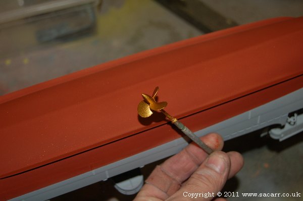
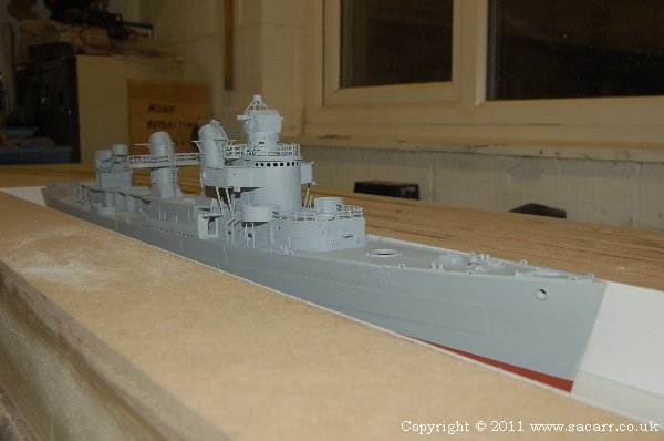
While some of the MDF was drying, the destroyer had the bottom of the hull painted. It would then have to dry for a while until it could be handled and masked for the black water line. The props were also sprayed.
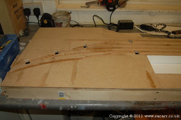
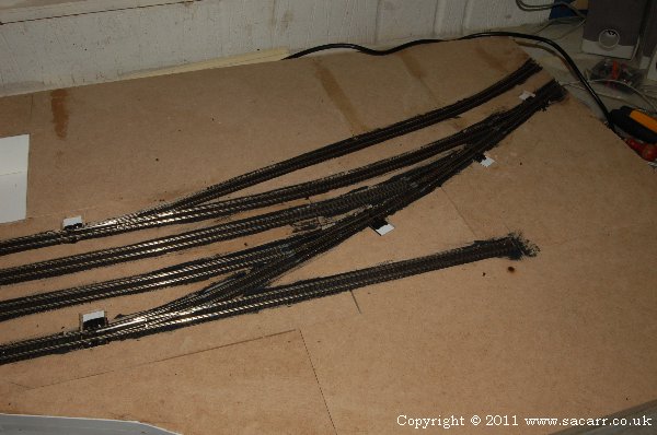
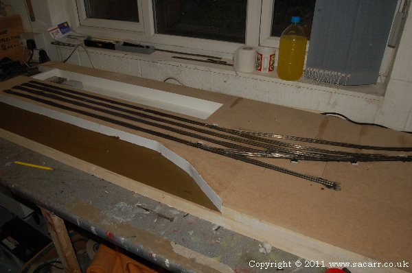
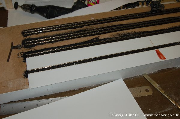
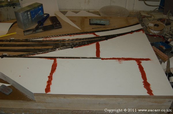
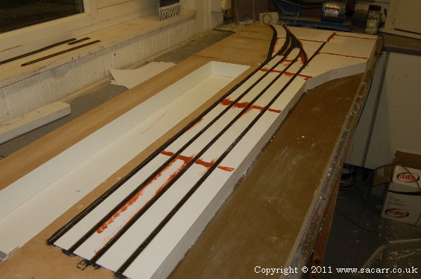
The track bed was finished along with the MDF packing to level the quayside with the tracks.
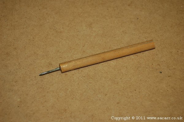
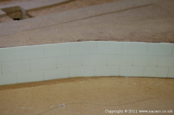
With that done, I was in a position to start adding the quayside wall. I used styrene sheet for this and scored the stone block effect on it with a tool I made from some 2mm steel wire sharpened on the sander and a piece of dowel.
While most of the wall will be under water, I wanted to show some texture. I plan to add the water in tinted layers, making it more opaque the deeper it gets, so the stonework will probably be visible for a little way below the surface, or that's the plan!
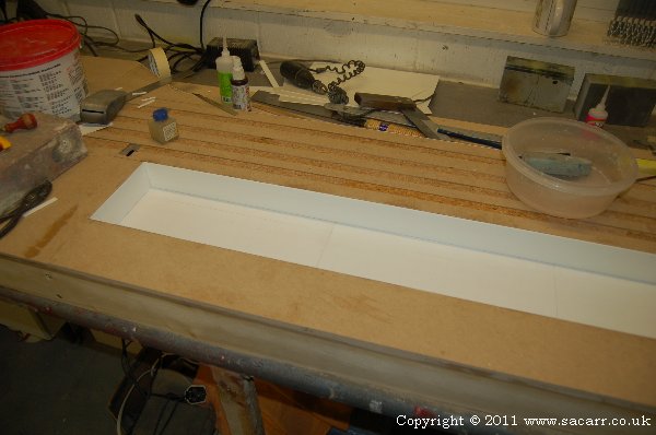
The drydock received the same treatment on the base and side walls, though the photos don't pick it up. Once painted and weathered, they should show nicely.
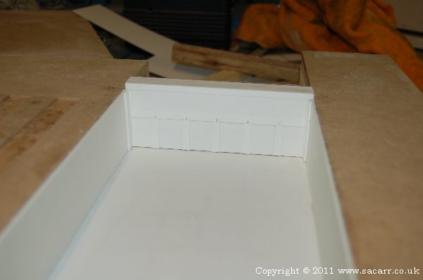
The drydock gate was made from some 18mm pine, skinned in styrene, with additional styrene strips added for the bracing of the steel gate. This will be painted separately and glued in later.
At present, the destroyer sits quite low in the drydock, but it will be raised slightly once it is mounted on the concrete/wood blocks that hold the hull steady once the water has drained away. At this scale, the blocks will probably be about 1/4 inch cubed with wooden wedges on top to match the hull shape.
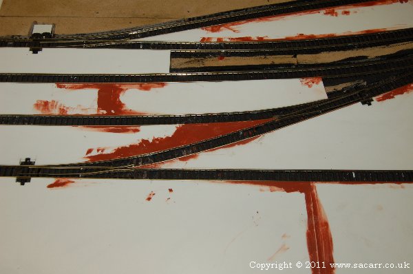
The track bed was painted black, short fly leads connected to the point motors and then track laying began. As each track joint was made, a few wagons were pushed across the joint to check for smooth running.
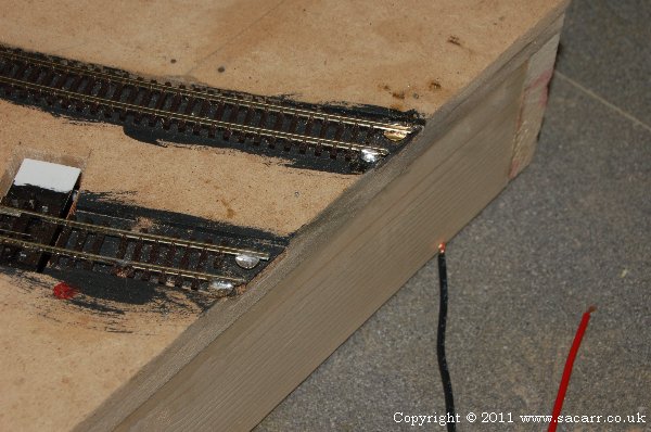
Normally, when the track reaches the end of the board, I use a copper clad board to form a sleeper that the rails are soldered to. This keeps them aligned in the correct location on the board for when the boards are joined. Because these tracks meet the edge at an angle, I used brass screws to solder the rails to.
While the layout will be DCC, these sidings are having isolation switches fitted to cut power to stationary locos. The various sidings had their power feeds added, and a loco run around to check the track work. With this complete, the way was clear for 'concreting' to begin. Individual slabs were to be scored into the surface after it was all fitted.
I started with the easy straight bits between the tracks in the yard, before moving to the curved sections. To get the curve, I placed a piece of paper over the track, and pressed the rails through the paper to leave a mark on the paper. This was then cut out as a template, drawn around onto the styrene and then cut out. It didn't require much trimming to get them to fit.
By the end of the first day concreting, I'd made good progress. It soon became apparent just how much area the quayside covered. It was going to take quite a bit of filling with details to make it look busy enough. By this point it was about the third week in February.
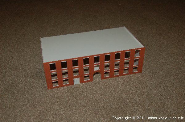
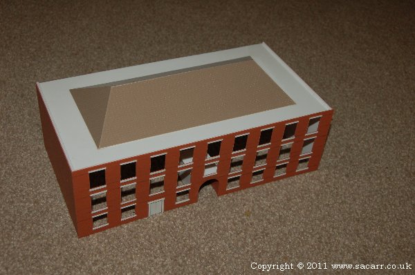
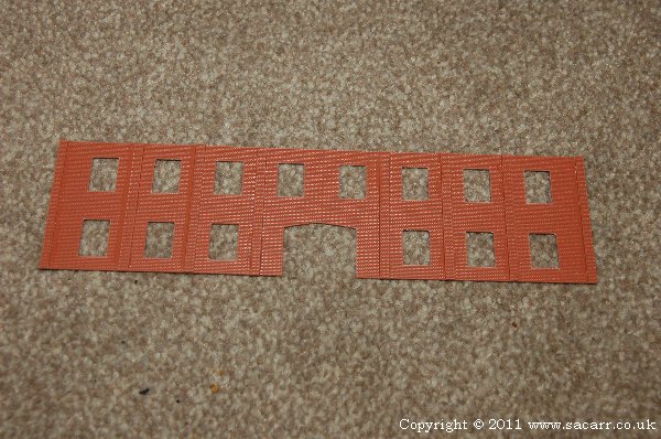
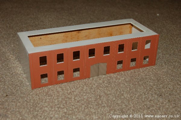
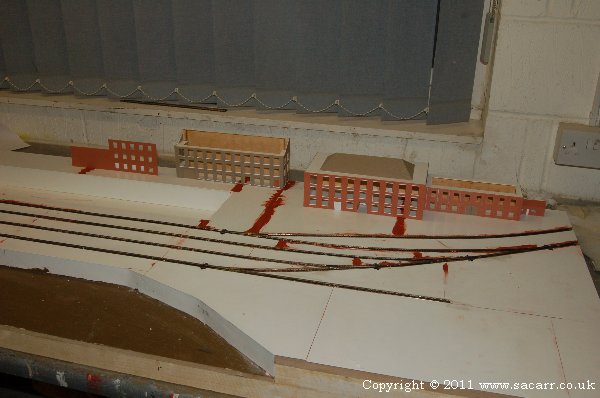
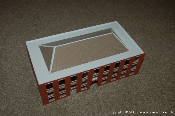
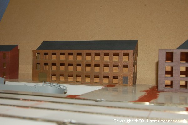
The next few days were spent building some warehouses. They were based on photos of real warehouses and use a mixture of brick and stone effect styrene. The first one is a three storey building with a sizable walkway around the roof. I suspect that roof will be an air raid wardens perch, as it makes a great viewing point to watch out for incendiaries on the other roof tops.
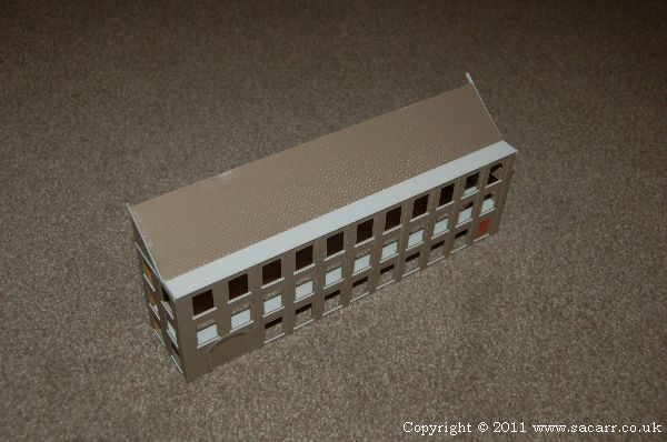
The second building is a two storey brick structure.
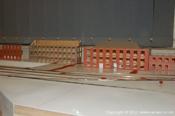
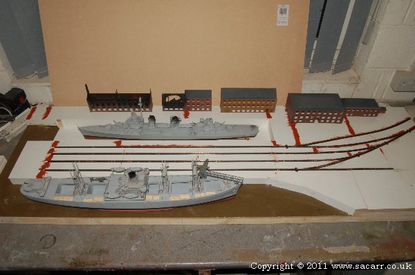
Warehouse three is another three storey building, but made from stone; and number four is split level, one half of which may be a burnt out shell. You can see that the concreting of the quayside is also complete.
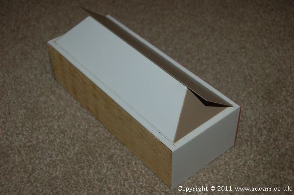
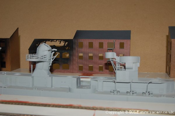
Building 1 ( counting from the right ) now has most of the roof fitted. I've used a 1/2mm plain styrene roof first to support the slate effect styrene, as it is quite thin and would bow otherwise.
Building 2 has had the ridge tiles added to the roof joints.
Building 3 now has a roof.
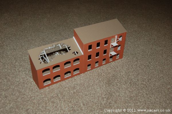
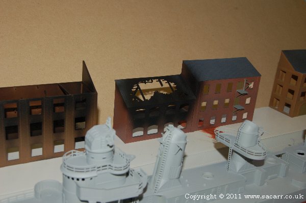
Building 4 and 5 are joined. Number 4 has a small crane and loading platforms to the upper levels. Number 5 has suffered from incendiary hits, loosing part of the roof and burning out.
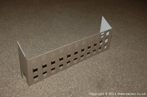
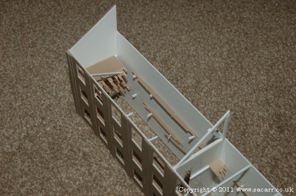
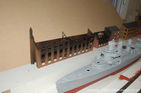
Building 6 is also going to be burned out, and just a shell.
I added a few remains of floors and interior walls, plus some burned away roof trusses.
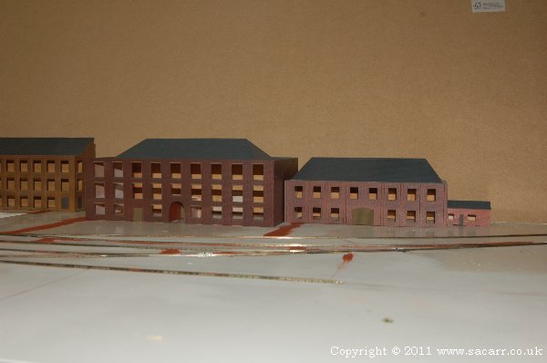
By late February, I was starting to paint buildings. Actually, probably about half of the day was spent painting and the other half constantly swapping colours and washing the airbrush out! The paints I've been using have a slight satin finish to them ( R/C aircraft paint ), so after the following photos were taken, they all got a matt clear coat to dull them down.
They were painted a mixture of brick and sandstone, according to the type of textured plasticard I used during the build. After the base colour was added, I dropped the airbrush pressure right down, until it was spraying a gentle mist of larger droplets of paint. A few different shades ( blacks, brown, red, greys etc ), were sprayed using this method to give a speckled finish to the paint, creating a more realistic tone and texture.
The burned out buildings had smoke staining added carefully with the airbrush after the main building colours had been painted.
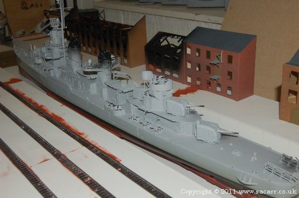
The water line has now been painted on the destroyer, and the black tops to the funnels, plus the turrets, mast etc. have been fitted. It still needs some rust streaks like the Liberty Ship had.
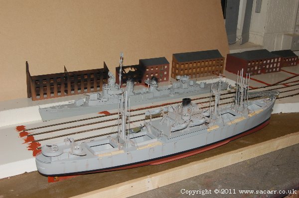
Here's a general view of the destroyer, in its almost complete state, plus a general view of the whole quayside scene to get a feel for how it will all look.
The next step was to rub down the whole quayside area, carefully scraping down any of the styrene that might interfere with the loco/wagon wheels. The whole 'concrete' area was then scribed to represent the concrete slabs that make up the quayside.
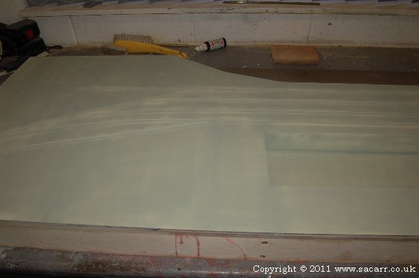
The track was then masked out and the whole area sprayed with a mix of cellulose and etch primer to check the joints and general surface finish. After it was dry, I went back over some of the joints with more filler, and this has now been left to fully harden.
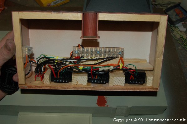
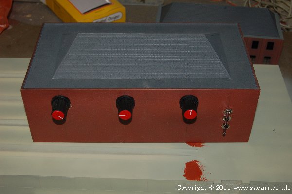
After a trip to the model shop for some supplies, I got down to wiring up the crane controls. They were going to be originally fitted to the instrument panel, but with that now being in a different location, I wanted to keep the controls near to the cranes.
The second warehouse was large enough to fit everything inside, and that faces the cranes, so it made an obvious place to fit them. The three rotary controls will operate either crane, selected by toggle switches. This keeps the cost down and also reduces the space needed for the controls. Three toggle switches switch power and servo signals from one crane to the other.
The back of the building still needs painting black, and the controls labeling to identify their operation.

Affiliate Disclosure: We may receive a commision from some of the links and ads shown on this website
(Learn More Here)