ModelRailroadForums.com is a free Model Railroad Discussion Forum and photo gallery. We cover all scales and sizes of model railroads. Online since 2002, it's one of the oldest and largest model railroad forums on the web. Whether you're a master model railroader or just getting started, you'll find something of interest here.
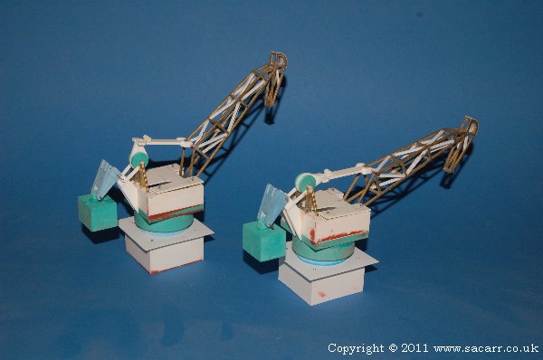
After the mechanics of the first crane were sorted and working, the second one was brought to the same stage.
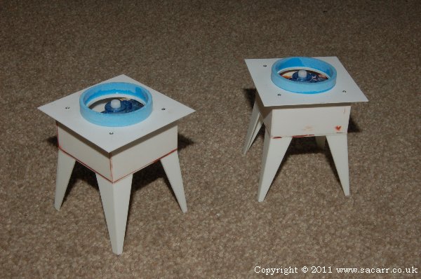
Next came the legs for the bases of the cranes. A styrene tube was added up the inside of one leg to guide the cable which will be attached to the hook, and the winch servo will be mounted under the baseboard.
While they were drying, four small links were made which attach the elevation cam to the balance weight. These parts and the main sections of the crane were then etch primed followed by grey primer. The cranes were then put to one side as further work was going to involve the fitting to the layout, which at this point didn't exist!
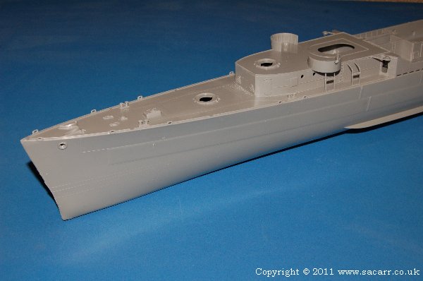
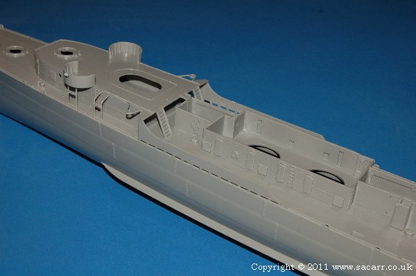
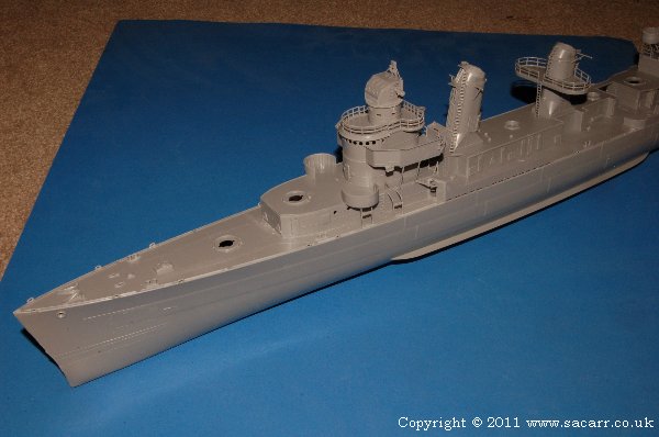
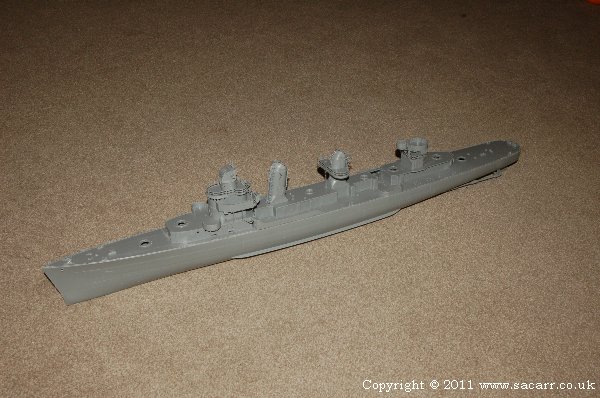
With the first ship done, and the cranes about as far as I wanted to take them without them attached to the layout, out came the destroyer kit. Since I've already covered the first ship build fairly well, I won't cover this one in as much depth, especially since it is being built pretty much straight out of the box.
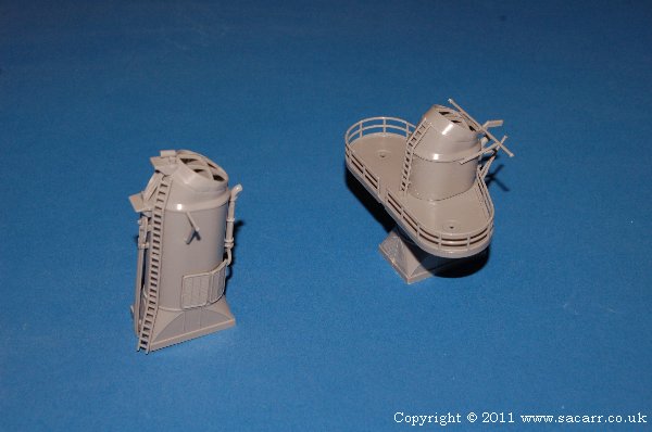
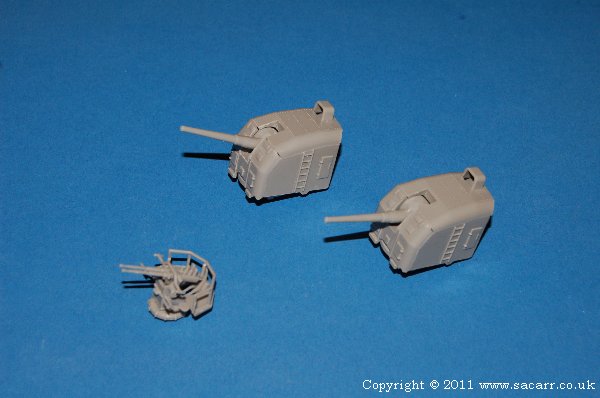
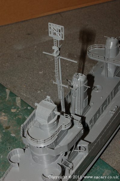
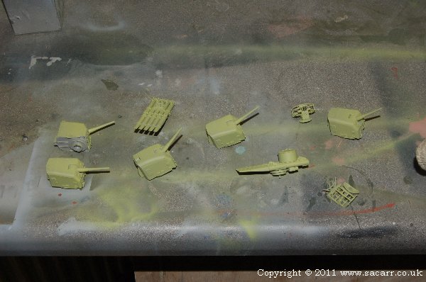
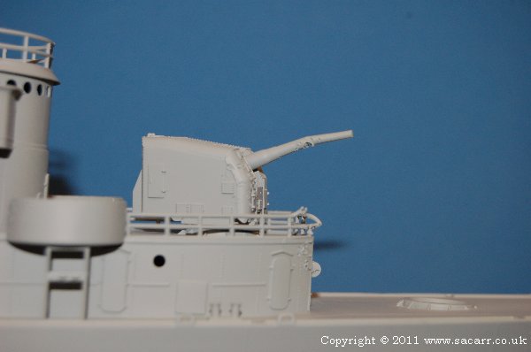
The hull was joined first, and while that was setting, I got the two funnels built, plus two of the main guns and the twin barrel anti-aircraft gun.
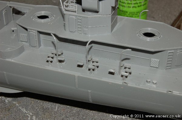
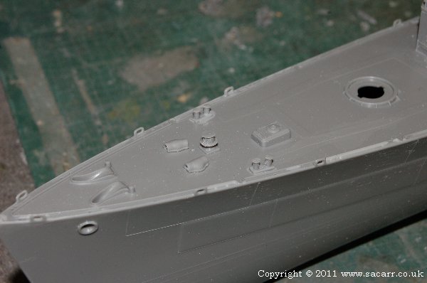
Building straight from the kit was much faster than the scratch building of the Liberty Ship. By the end of the first day, I had the deck on and the first sections of superstructure in place.
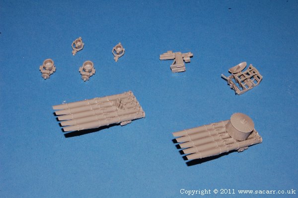
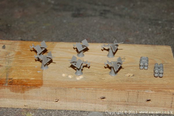
The depth charge launchers all had the depth charges sanded off, and a small radius filed into the launcher. Somewhere on the floor of my workshop is one of the launchers! Fortunately I had spares from the other kit to use.
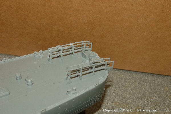
The stern depth charge rails also had the charges drilled and filed away, which was a fiddly job as the rails were pretty fragile with the plastic cut away between them.
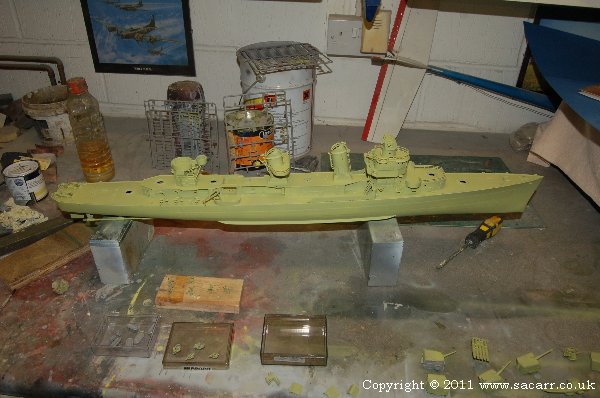
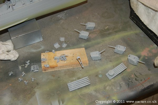
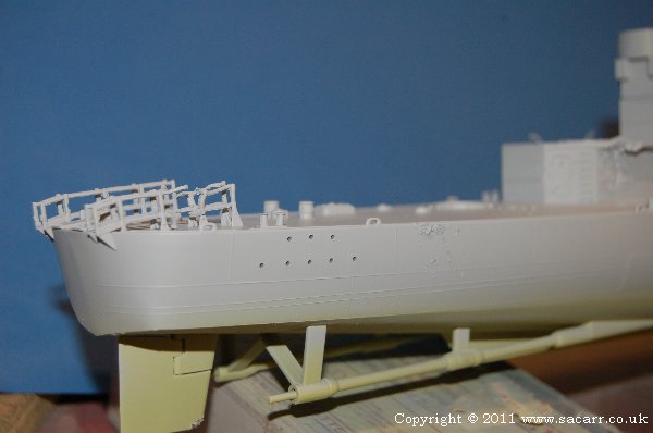
Here's some of the smaller parts in grey. In the background, the hull can also be seen in grey primer.
Since the ship will be in dry dock, it needs to be there for a reason. So I wanted some battle damage, but not trashed, and there needed to be a reason for being in the dry dock, not just superstructure repairs.
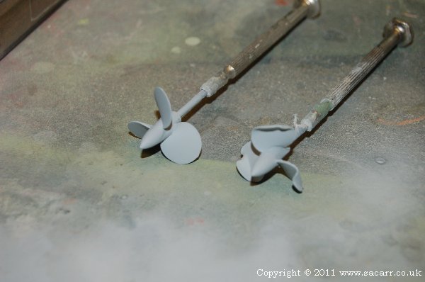
So, an easy reason for being in the dry dock was a new prop, so one has been mangled. Whether this was caused by combat or the captain running aground is classified.
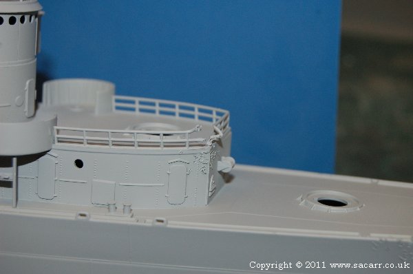
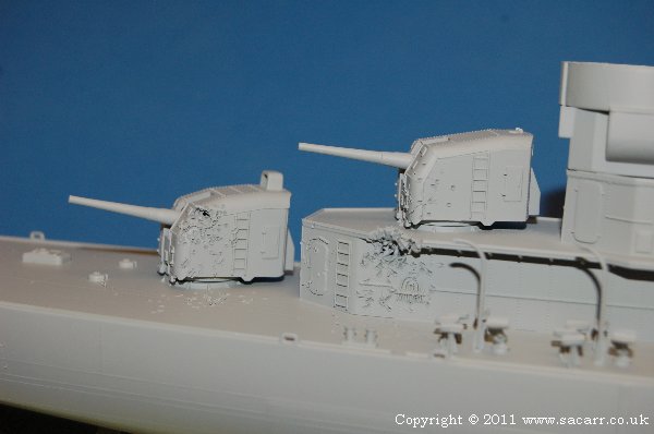
After a search on the internet, I found some minor battle damage photos to work from. Much of the damage was smallish pitting of the ship from shrapnel strikes. The easiest way to reproduce this was with the sharp point of a hot soldering iron, melting into the plastic. A number of areas were targeted.
One of the depth charge rails on the stern was also damaged. The rails on this side didn't look 100% neat after carving out the depth charges, so battle damage was a good way to hide this.
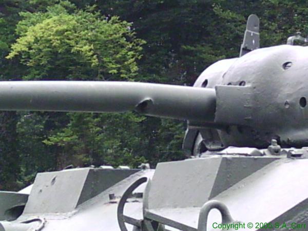
One of the front turrets had the barrel damaged in a most unusual way, based on real battle damage that I saw on a Sherman tank in France. A 75mm round had hit the bottom half of the barrel, taking out a chunk and kinking the barrel down.
Here's the Sherman damage.....and the model.....
If I hadn't seen it for real, I wouldn't have believed it.
Thank you. I've really enjoyed the build so far, so much so I can hardly call it work! Now I haven't forgotten that this is a model railroad forum, so for those wondering where the rails and trains are, we're about at that point in the story!
While there were still a few small details to do on the destroyer, plus some painting, the beginning of February 2011 saw trips to the model shop for track and points, plus the hardware store for timber.
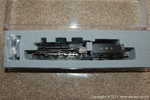
A Graham Farish DCC ready 'Black 5' was bought so that I could test the sections of the layout as I went. I had also ordered the Digitrax Super Chief 8AH starter set to operate the layout. Having never used DCC, it took a little while to wrap my head around its operation, but now that I understand it, I'm very impressed with its operation anf flexibility.
Now here's the bit you've all been waiting for; the start of the bench work. The first of thirteen sections!
I took some time planning out how the 8x4 sheet of MDF was to be cut. As a result, I've got three baseboard sections out of the one sheet; both quayside sections and one other. I didn't buy any timber for legs yet, as I can work on the layout on my main building bench, and it saves space not needing to store completed legs. They can be built at a later date.
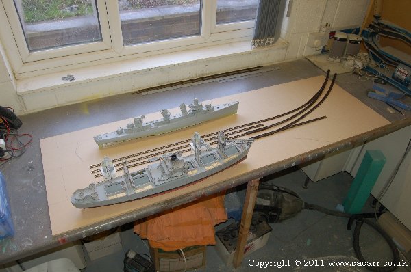
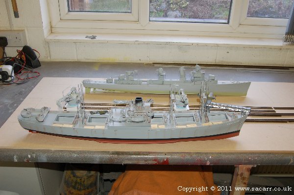
With the basic MDF base cut, I then marked out roughly where the quay, drydock and track needed to go. Both ship models were used to get everything looking right. I've always found that when a track plan is drawn in the planning stage, it usually needs things adjusting slightly here and there to get things to look right at full size.
On the first draft of the quayside, it was to be 1600mm long, but this has been enlarged to 1800mm to give a little more space to work in. The width has also been increased slightly when I realised I had more room width than I first realised. This is because the sections down the side of the layout narrow by 6 inches giving a bit more walking space down each side of the quayside.
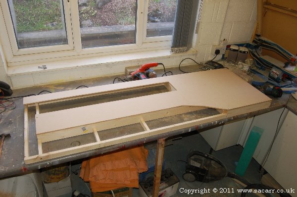
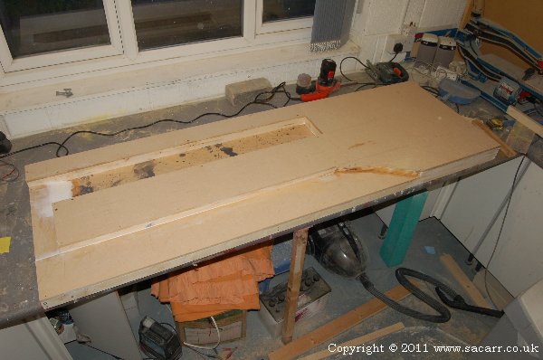
With the layout of the quayside finalised, I cut the openings for the water and drydock, and added the timber framing. This is mostly 3 x 3/4 timber. For a permanent layout, I might use larger timber, but this needs to be kept moderately lightweight so it can be transported to its final home. Additional bracing can be added at a later date.
This was followed by adding the floor the drydock and sea bed along side the quayside. The dark splotches in the drydock floor are as a result of a paint tin exploding after falling off my bench, but that will be covered over anyway.
The quayside surface needs raising a bit too. Once the track is on the cork roadbed, the rail tops will be a little over 1/4 inch above the baseboard, so I have some 6mm MDF to cut and fill the spaces between the track before the final styrene quayside surface is added.
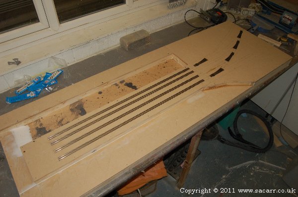
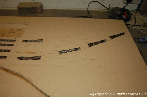
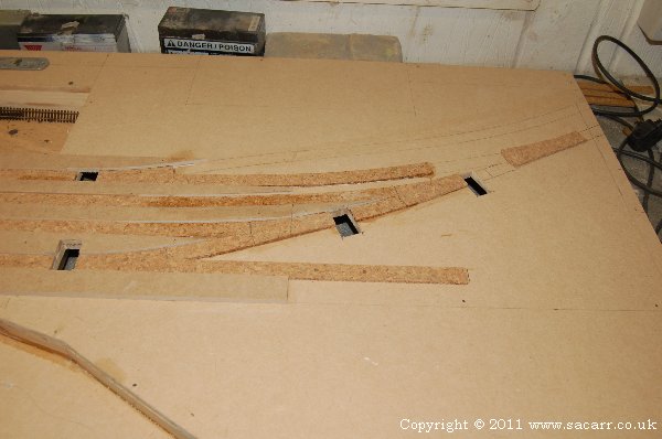
With the board complete and drying, I started marking out the position of the track and points. The next stage was to cut openings for the point motors and to glue down the cork roadbed.
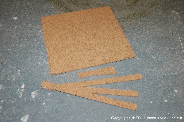
The cork trackbed was cut from 12 inch cork floor tiles, bought at B&Q. All my previous layouts had the cork sliced with a scalpel, which is very hard work on the fingers as the friction of the cork makes cutting an effort! This time round however, I had a bandsaw, making the cutting a piece of cake. In addition to strips slightly wider than the flexitrack, I also cut some point shaped blanks.
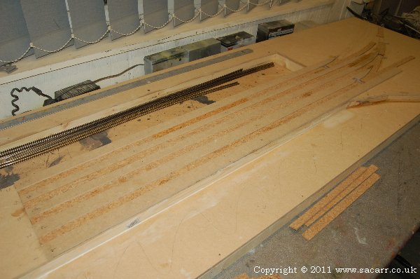
As I've done in the past, the cork is glued down mostly with PVA glue, but especially on sections that are curved, I add a drop of cyano acrylate glue at each end and in the middle. This instantly holds the cork in the correct shape while the PVA gets a hold. The holes for four of the point motors have also been cut, and some of the 6mm MDF has also been fitted.
This general view shows the four cork trackbeds and the MDF either side to raise the quay level.
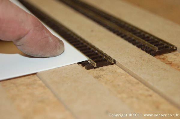
Styrene was used to form the concrete of the quayside, and this shot shows how it sits against the rails. I need to use a piece slightly thicker than that shown, but will need to chamfer the bottom edge to clear the chairs on the sleepers.