Proto 2000 SD7 Lighting query


Smudge617

Well-Known Member
Morning All
I'm new to the HO scale and American Locos in particular, (I normally model UK steam in OO gauge). But have decided to go in a new direction.
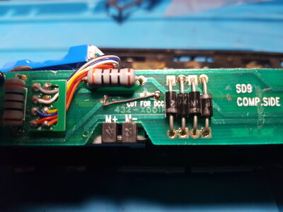
My query is this, I have an SD7 loco that is fitted with an 8 pin socket and 12v bulbs front and back, I've fitted a Digitrax decoder and all is well, runs beautifully, lights work, great, but I want to swap out the 12v bulbs for LED's, I've done this many times on UK locos, no problem, but I cannot get them to work on the SD7 and I cannot work out why, I know it's not the polarity, and I've tried with and without resistors, I've refitted the original lights, and they still work. There is a wire marked "cut for DCC" but there seems to be some indecision on several forums as to whether this wire needs to be cut or not. Do I need to cut this wire? or as seems to be the case, swap out the circuit board? If it's a new circuit board which would you suggest replacing it with?
Many thanks for your help.
 
Welcome to the forums.
If the circuit board really puts out 12v DC, you've probably already ruined the 1.5-4v LEDs. If your SD7 has bulbs, they are likely 1.5v, not 12v. If so, it's possible the board is not sending enough voltage to the LEDs to light them, or you may have the LEDs connected in reverse. Try swapping the leads to them, and see if they illuminate.
 
I have an SD7 loco that is fitted with an 8 pin socket and 12v bulbs front and back, I've fitted a Digitrax decoder a... but I want to swap out the 12v bulbs for LED's, ...There is a wire marked "cut for DCC" but there seems to be some indecision on several forums as to whether this wire needs to be cut or not.
How is the wire marked "cut for DCC"? A tag on the wire? Where is this wire coming from and going to?
 
Hi, Thanks bnsf

Sorry I misspoke, by 12v I meant on DC power, the original 1.5v bulbs I have replaced back into the loco, and they still work.
I know I don't have the polarity reversed, I've checked and double-checked that the LED's are the correct way round, I've installed around 35 loco's and coaches with LED lighting so I'm aware of how easy it is to get it wrong, so I always triple check which way round the LED is connected. (and on the offchance I did get it wrong, I did reverse the wiring, still nothing).

It could well be that the LEDs aren't receiving enough power to work, but I'm replacing the bulbs with 1.5v LED's so there is no reason they shouldn't work unless there is a problem with the board. I've tried 3 different Decoders (Gaugemaster, Zimo, and a Laisdcc) Loco is fine, original lights also fine, fit LEDs, zilch, nada, bugger all, never come across this issue before,

As I've never fitted LED's with this type of loco circuit board, usually, I'll direct wire in, or use a directional lighting board, but I'm wary of doing either as I don't know how this would affect the motor or performance, and, as the cost of postage from the US. to the UK for any parts I might need to replace if I screw up is usually double/triple the cost of the actual item, I don't want to make what could be an expensive clusterf*** of doing this.
How is the wire marked "cut for DCC"? A tag on the wire? Where is this wire coming from and going to?
I'm not familiar with this type of board so I have no idea where it's from or too, but this is the board
 

Attachments

  • SD7.jpg
    SD7.jpg
    364.1 KB · Views: 100
I'm not familiar with this type of board so I have no idea where it's from or too, but this is the board
Oh I see. You did not replace the factory board with a decoder but used the existing 8 pin plug for the decoder. I unfortunately cannot find the schematic diagram for that loco's board. And not being able to see enough to map it out for myself, I would assume the folks who made the DCC ready board know what they were talking about and cut the trace. I can say that trace to be cut has something to do with the lighting as the motor traces are obviously on the other side of the board and the power traces are along the edges. Actually looks like it has been cut at one time and then re-jumped.
 
This is what I find weird, it has 1.5v bulbs, which work on/off on F0 using the existing board, and any decoder, if I'm using the same voltage LEDs it should still work as if it had bulbs fitted, so I fail to see what this trace has to do with the lighting, or have I missed something?
I'll cut the trace and see what happens, push comes to shove I'll have to replace the board, I can get a DH165LO here in the UK, I'm told it's a decent replacement for the SD7's factory board.
 
The only LEDs I know of that are 1.5V are red and white usually takes 3V so I am guessing the board in the loco isn't letting enough 'lectricty through to light the LEDs. Taking the circuit board out shouldn't have any impact on motor performance. The resistors and diodes on the board are only for the lighting.

I just looked and found an SD9 board in the parts box. It also has the little jumper soldered over the "cut here for DCC". It looks like cutting that only allows front and rear light circuits to be independent. You could also jump over all the components on the board and go from the soldered plugs on the back of the board to the light outputs. Unless using a decoder with resistors, you will need to add one for each light.
 
Last edited:
This is what I find weird, it has 1.5v bulbs, which work on/off on F0 using the existing board, and any decoder, if I'm using the same voltage LEDs it should still work as if it had bulbs fitted, so I fail to see what this trace has to do with the lighting, or have I missed something?
That is a common confusion factor. Diodes are not light bulbs and do not behave the same way. Diodes (even light emitting ones) are not voltage dependent. They are current dependent. Once a diode hits a threshold voltage it will pass as much current as it can before it blows out. That is why they have to have resistors in series to limit the current. This is over stating the case, but it could be 1000 volts as long as that voltage doesn't push through more than the max amount of current.

As the prior poster (kjd) noted it could be that the 1.5v output to the lamps is not past the diode's threshold voltage, so it never activates.

But I agree with you the trace has been puzzling me since you first posted the picture.

I'll cut the trace and see what happens, push comes to shove I'll have to replace the board, I can get a DH165LO here in the UK, I'm told it's a decent replacement for the SD7's factory board.
Or you could just solder the jumper back over the cut.
 
Last edited:
Hi.

I've tried red Led's as they have the correct voltage, but still nothing, but weirdly the original bulbs work. I think it could well be an issue with the board itself, but I'm useless at electronics to be certain, but as you seem to understand this, what exactly does this board do, as far as I can see this is simply a lighting board, what else does it do?
 
I've tried red Led's as they have the correct voltage, but still nothing, but weirdly the original bulbs work. I think it could well be an issue with the board itself, but I'm useless at electronics to be certain, but as you seem to understand this, what exactly does this board do, as far as I can see this is simply a lighting board, what else does it do?
It does two things. It provides an interface for the DCC controller, and as you summized it provides "constant" and directional lighting for DC operation.
 
Aha! the penny drops, very few people use these in the UK, so please excuse my ignorance. I actually thought it was an integral part of the Loco. I've fixed directional lighting to a few of my Loco's and most of my coaches but never used a board to do it, normally I would hardwire a harness to the motor, (if there's enough room.) and then solder lights to the harness, and fit a decoder of choice, I find it makes problem-solving easier as you don't need to unsolder the decoder if there is a fault and you don't know whether it's the decoder or the Loco, and obviously if you want to upgrade your decoder, it takes seconds to do, same as using a board.
I haven't tried to do that to this Loco as I'm unfamiliar with the motor mechanism, wiring, etc. and I really don't want to mess it up, I doubt I would be able to fix it if I did, hence replacing the board. Thanks guys, appreciate your help.
 
OP wrote:
"I can get a DH165LO here in the UK, I'm told it's a decent replacement for the SD7's factory board."

I use Soundtraxx MC2H104at boards in my Proto 2000 SD7s/SD9s.
But the Digitrax DH165LO should work, too.

MUCH better than the factory board and an 8-pin decoder.
These work fine with LED's I get from ebay that have the resistor already soldered to the lead, with shrink-wrap installed by the seller.

I would suggest you fully disassemble the trucks on these, and clean out all the old "peanut butter" grease.
 
I looked at the Soundtraxx board you mentioned, looks good, and available in the UK, so may well get one. I have two boards already (chinese knockoffs), will try one of them in a Hornby class 37 diesel I have but I think the Soundtraxx board would be the way to go on the SD7, just need to work out on the SD7 if I can fit two led's either end, assuming that depending on the direction of travel, the headlight would be showing red at the back when solo, not going to fit ditch lights,too fiddly for me to fit.
But I have a question for you, the instructions show an exploded view of the body, how does it come apart, my idea is to remove the clear plastic lens, drill two holes for the led's and fit them that way, doesn't matter if there both supposed to be white, larger resistor would make it dimmer in reverse, or am I trying to do too much?
 
UPDATE
I can now put Iron Horseman out of his wonder about that trace on the motherboard of the SD7, I now know what it does..........
When cut, it will only run on DCC, no more DC, now, to solder the bloody thing back on.........not.
I'm following Mr. J Albert's advice, and getting a new board. I love my (where did all my money go) hobby :)
And it gets even better, finally got an LED to work with the board, 🥳 grain of wheat size, anything bigger and it's a no-no, good job I'm getting a new board really.🙂
 
UPDATE
I can now put Iron Horseman out of his wonder about that trace on the motherboard of the SD7, I now know what it does..........
When cut, it will only run on DCC, no more DC, now, to solder the bloody thing back on.........not.
That is surprising. Usually on a DCC loco, to turn on off DC option one would set CV-39 differently.

I am currious now, did the LEDs work in DCC only mode. From your other comment about grain of wheat, I would guess not.
 
That is surprising. Usually on a DCC loco, to turn on off DC option one would set CV-39 differently.

I am currious now, did the LEDs work in DCC only mode. From your other comment about grain of wheat, I would guess not.
Depending on the value used in CV39 you switch one or the other off or use both as you know, but I've found that when trying to run a DC loco by selecting 0 (I'm using a Digitrax controller so 0 is for a DC only loco), the motor just hums which is not a good sign for the motor, but then they all do that, I'm supposed to be able to run one loco on DC according to the manual, and all my decoders are set to run on analog or DCC, the one I've been using is a brand new Digitrax, I haven't even changed the address, so it's still preset to run on either. I've tried LaisDCC, Zimo, and Gaugemaster decoders and they won't run on DC either on my layout, so it's probably the controller, I have to use my RR if I need to fault find in DC.

And yes, your right I cannot get a LED to work with this board, on DCC or DC I've even soldered one on with a 1K resistor, it just won't play ball. But fit a bulb, or grain of wheat, works every time, so I've borrowed a cheap lighting board from a friend of mine (the same board you get in the US for $10) and over this weekend I'm going to try that, and see if it will work, (the Soundtraxx board won't arrive till the end of the week) if it does then it has to be the board. If it doesn't work, I'll try the Soundtraxx, next in line if that fails it's hardwiring it in, which I hate doing, if that doesn't work I'll put it all back as originally manufactured and just have two very weak lights.
But I really would like LED's, having just one headlight doesn't do much really, I'd like to add all the running lights it should have it just adds a little more, how can I say it, Oomph!!
 
light.jpg
Finally, I now have working lights on the SD7, DC (above), and DCC. Now if only I can remember which is supposed to be the front end of the loco.:eek:.
light2.jpg
 
The air tanks go toward the front. The front headlight is lit in your photo.
edit: If the short hood is front. Since diesels go the same in either direction, there is often a letter 'F' stenciled by the stairs on one end. That means, you guessed it!, Front.
 
Last edited:


Back
Top