ModelRailroadForums.com is a free Model Railroad Discussion Forum and photo gallery. We cover all scales and sizes of model railroads. Online since 2002, it's one of the oldest and largest model railroad forums on the web. Whether you're a master model railroader or just getting started, you'll find something of interest here.
Page 1 of the TCS Z2 manual has a diagram on the right hand side that shows the wiring. Looks like they follow NMRA standards. The orange and grey go to the motor. The black and red go to the track pick ups. I assume the John Bull does not have a working headlight so the blue, white, and yellow wires can be cut off to save space. If you want to make the headlamp working save the white and blue.
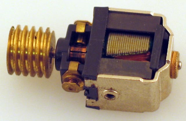
The Bachmann site does not have a manual for the John Bull but the motor should look like the photo below (courtesy of Bachmann web site). The grey and orange wires would attach to the two brushes shown either directly or indirectly. The decoder might fit in one of humps of the loco itself. If not there should more than enough space in the tender "house".
Just one thing to add: make sure the motor brushes are isolated from the motor frame, or that the motor frame is isolated from the loco frame. Best way to do this is with a multimeter. if your motor is not isolated from the rail pickups, you'll blow the motor drive when you apply power. This should be in your TCS instructions. Have fun...it's not hard!