working with foam below your track


railBuilderDhd

Active Member
Hi Guys,

I'm working on the foam below my track and have questions about what others are doing or should I just purchase the WS foam risers and not bother with this myself.

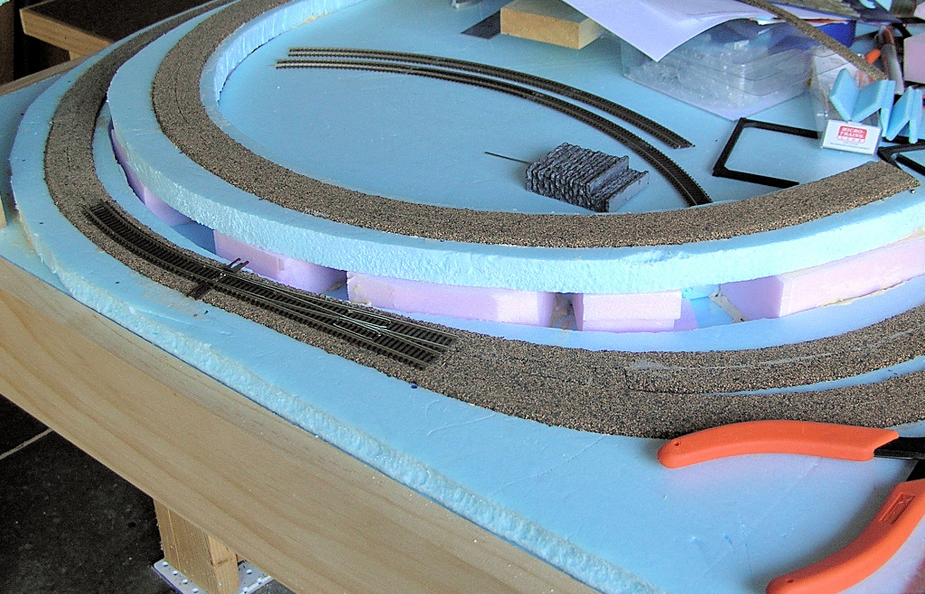
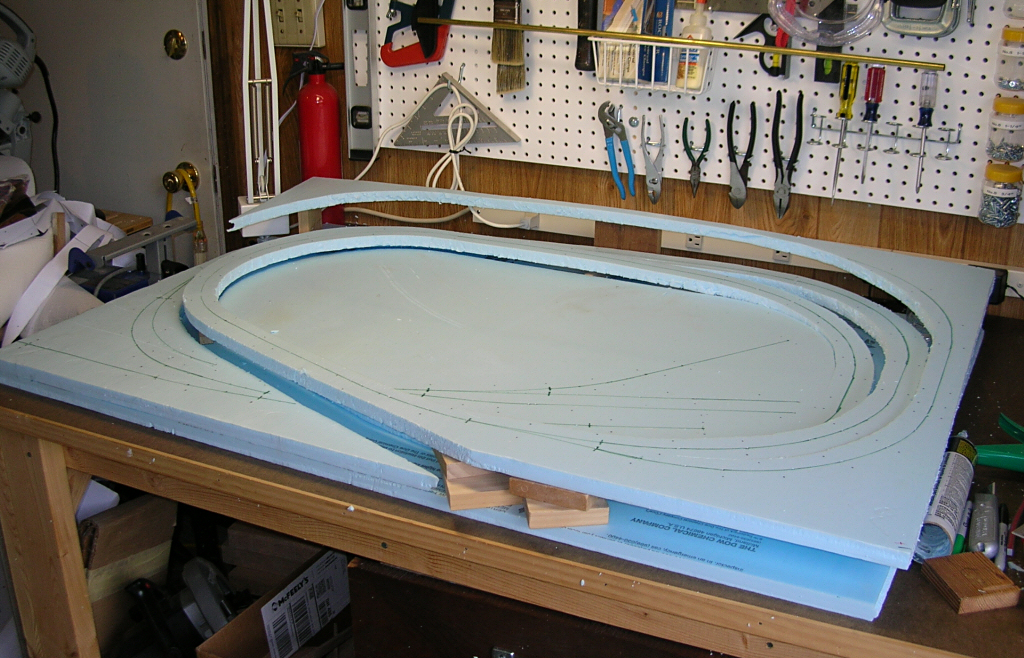
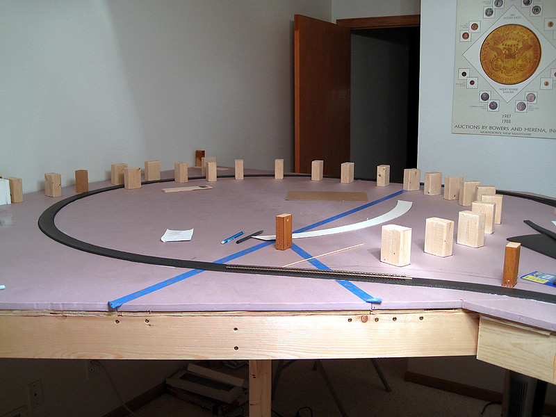
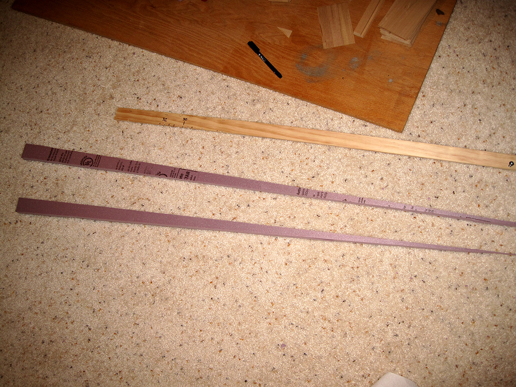
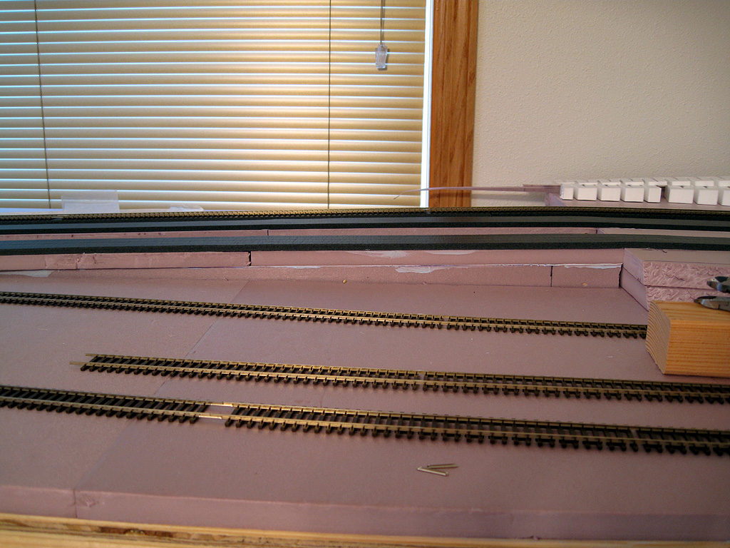
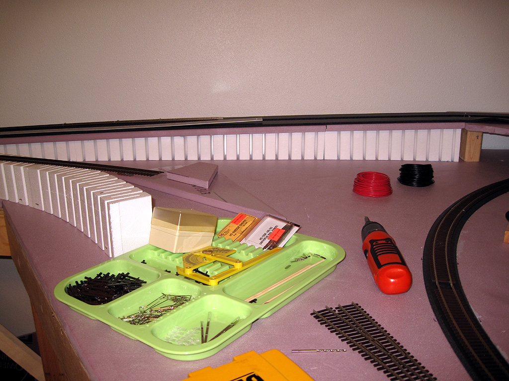
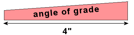
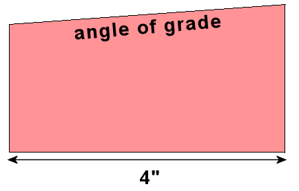
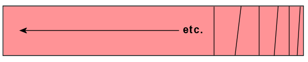
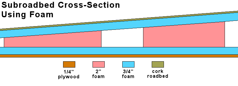
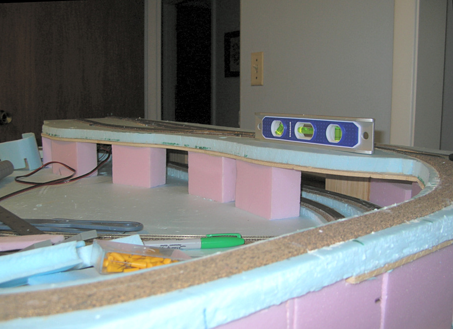
I'm trying to create a grade about 2°. When I cut the foam I'm not getting a even surface to run my track. I was thinking I could smooth out the surface with hydrocal or plaster or even sculptymold to get the smooth level grade for my track to run. I was thinking it shouldn't matter much as the cork will be on this surface and the track on that. As long as the grade done evenly the surface material shouldn't mater. CORRECT?

The other option I can purchase the WS foam risers and just use them. I would love to hear what others have done or are doing.

Dave
 
I have 2 inch foam and for my incline and down hill I bought 4 by 36 sheets of basswood that I laid my roadbed on. For the rise and fall I cut pieces of foam from thin to thick and spaced them maybe 6 inches apart under the basswood. Afterwards I crumbled up newspaper and laid it next to my hills and used plaster cloth to make it look like hills.
 
Last edited by a moderator:
Hi,

I created a jig to cut foam with a hot wire cutter to create the correct slopes.

If I had it to do over I would just go with WS products or just cut the plywood underneath my foam and bend it to the required slope.

Frederick
 
I used foam risers -- the pink foam below -- to support the foam sub-roadbed. I cut the tops of the risers to the correct angle for whatever grade I needed. The foam is easy to cut on a miter saw.

- Jeff

grades_1024.jpg
 
Jeff, I may have to try that option before I end up buying all WS foam risers. Since this is the base of the track I'm thinking it's best to just go with WS foam.

Dave
 
Jeff,
I was able to try your option on a section I had been working on and it seems to be a good idea. I'll post photos soon. The last thing I'll need to work out is the transition from flat to incline and back to flat. Off to learn options for that today.
Thanks folks.
Dave
 
Hi Dave -

One way to ensure smooth transitions is to create your sub-roadbed using the cookie-cutter method. In the photo below, you can see how I cut a layer of blue foam using this method. Then I supported the blue foam using the pink foam risers as shown in post #4 above.

The cookie-cutter method leaves the sub-roadbed in one piece so that it naturally forms smooth transitions. This method has been used successfully in both HO and N-scale. The HO layout I saw used 1-inch foam for the cookie-cutter portion. I used 3/4-inch foam on my N-scale layout.

- Jeff

cookie_cutter2_big.jpg
 
I can't promise this is the best way, but here's what I've tried so far. My layout is (mostly) 1/2" foam over 1/2" plywood:

33340210192_4dc4367cf8_c.jpg


Just like you, I figured I'd save some money and make my own risers with all the extra foam. Simple, right? Just figure out how much rise over what length, and cut diagonal pieces out of the foam:

32682191623_6f6ca1baa2_o.jpg


The problem, as you discovered, is that no matter how carefully I cut, I could never get perfectly square tops, and even worse, I could never get two diagonal pieces to exactly match. I did the cutting with a new xacto knife blade and long straightedge fixed in place with T-pins. After much trimming and re-cutting, I did get enough workable pieces for the first grade. What made this possible was that I was placing a half-inch piece of foam OVER the diagonal piece. When glued in place, that combined with the roadbed on top damped out the imperfections and did produce a workable grade:

33368011511_2fe907bd8c_o.jpg


But after that experience, I decided to break down and get the Woodlands risers. I am still using the foam sub-roadbed on top of the risers, however. I've actually managed to get a double-track main on top of a single riser, by cutting a strip of pink foam and gluing it centered on the foam riser. In the pic below, the grade in the back is complete, the one on the left does not yet have the top foam layer added. Eventually scenery will be added to the sides of the grade.

Good luck to you, -Eric

33340209692_fa32c8667c_o.jpg
 
I have taken the Prototype into consideration on a few grade leveling issues and simply use ballast.

I have one particular corner that is at the beginning of a grade and most of my locos would run across without issue. My Steamer, though, would derail it's trailing trucks every time. Turns out the transition was just a touch too abrupt in one spot, so I simply popped up the track to a more level transition and ballasted away. Applied glue to hold it in place and all was good.
 
IMG_6277.jpgI've been working on my inclines and so far I'm liking the way they are going. Much to do but it's going now.
 
Last edited by a moderator:
I used foam risers -- the pink foam below -- to support the foam sub-roadbed. I cut the tops of the risers to the correct angle for whatever grade I needed. The foam is easy to cut on a miter saw.

- Jeff
You used a miter saw in order to get consistent angles, correct?
Any reason you used two different color foams?
 
Hi Dave -

One way to ensure smooth transitions is to create your sub-roadbed using the cookie-cutter method. In the photo below, you can see how I cut a layer of blue foam using this method. Then I supported the blue foam using the pink foam risers as shown in post #4 above.

The cookie-cutter method leaves the sub-roadbed in one piece so that it naturally forms smooth transitions. This method has been used successfully in both HO and N-scale. The HO layout I saw used 1-inch foam for the cookie-cutter portion. I used 3/4-inch foam on my N-scale layout.

- Jeff

cookie_cutter2_big.jpg

What tool did you utilize to make those long cuts,....razor knife, kitchen knife, etc?

Any particular reason for 2 different color foams?
 
What tool did you utilize to make those long cuts,....razor knife, kitchen knife, etc?

I used cheap serrated steak knives to cut the subroadbed pattern in the 3/4-inch blue foam.

You used a miter saw in order to get consistent angles, correct?

Yes, I used a miter saw to cut the angles on the foam risers.

The sheet of pink foam I purchased was 4x8 feet by 2 inches thick. I had the home center cut the sheet of foam in half so I could fit it in my SUV.

At home, the first thing I did was to use a table saw to cut 4-inch-wide "planks" of foam, resulting in pieces that were 2"x4" by several feet long:

pink_foam_plank1.png


Then I used the miter saw to cut risers that were the correct height with the proper angle on one side. For any given grade, the angle is the same for every riser, but the height varies. A riser near the start of the grade looks something like this:

pink_block_profile0.png


As the grade rises, the block must be taller, but the angle stays the same:

pink_block_profile1.png


The bottom of the block is always flat and square with the sides. Only the top side of the block is cut at an angle. The cutting pattern on the foam plank look more less like this:

pink_foam_cuts1.png


Any reason you used two different color foams?

At the home center, the 3/4-inch foam was available only in blue. The 2-inch foam was available only in pink. That's the sole reason. It makes for a nice contrast of colors in the construction photos!

It all sounds pretty straightforward when I describe it here. In reality, I made many mistakes at the start and discarded quite a few foam risers. In some cases I miscalculated the angle and cut several risers before realizing my mistake. There are places in the layout where I had to insert little chunks of foam to compensate for poorly-cut risers. All these errors are now thankfully hidden under scenery!

- Jeff
 
Last edited by a moderator:
thanks Jeff,

Is there a preferred glue YOU used to glue risers to sub-roadbed, and to the 'lengths of ramps' as well?

What did you set the bottoms of the risers on where you fabricated the ramps by slicing them out of the 2" base sheet?

What material/method did you utilize where the upper track passes over a lower one (if you had such a spot) ??
 
Is there a preferred glue YOU used to glue risers to sub-roadbed, and to the 'lengths of ramps' as well?
For gluing foam to foam, I used Liquid Nails Heavy Duty Construction Adhesive:

liquid_nails1.png


It's probably overkill for this project, but I had some on hand. Not all Liquid Nails products are safe for use on foam, so consult the label or test it on a scrap of foam. For attaching cork roadbed to the foam and track to the cork, I used latex caulk.

What did you set the bottoms of the risers on where you fabricated the ramps by slicing them out of the 2" base sheet?
I'm not sure I understand this question, but maybe the illustration below will answer it:

subroadbed_cross_section1.png


The plywood layer provides a surface for mounting turnout motors, circuit boards, terminal strips, etc., under the layout. The bottom layer of blue foam provides the base for scenery and for track that is not elevated or on a grade.

This all rests on the benchwork, which looks like this:

table_frame1.jpg


What material/method did you utilize where the upper track passes over a lower one (if you had such a spot) ??
I do indeed have such a spot on my layout where the branch line passes over other tracks. For that section, I glued 3/4-inch foam to 1/4-inch plywood. Then I supported the section with foam risers where I could and with blocks of wood where there was not room for foam risers:

branch_supports2.jpg


- Jeff
 
I'm not sure I understand this question, but maybe the illustration below will answer it:

subroadbed_cross_section1.png


The plywood layer provides a surface for mounting turnout motors, circuit boards, terminal strips, etc., under the layout. The bottom layer of blue foam provides the base for scenery and for track that is not elevated or on a grade.
I see now where I was not understanding your method,....your foam subroadbed was two sheet thicknesses of foam from which you cut the 'grade' out of only the upper thickness, leaving the other one as the 'base' to set the risers on.

I had been imagining more along the idea of plywood construction where the 'grade' (elevated roadway would span a longer distance between risers), and that might require a stiffer foam roadbed to span those distances.

I do indeed have such a spot on my layout where the branch line passes over other tracks. For that section, I glued 3/4-inch foam to 1/4-inch plywood. Then I supported the section with foam risers where I could and with blocks of wood where there was not room for foam risers:

branch_supports2.jpg


- Jeff
I have in the past sought to minimize the overall height of the upper railway when it passed over a lower railway so that I did not have to ramp that grade up so much (minimize that grade). In that pursuit I would want to make that subroadbed for the upper railway to a very minimun thickness where it passed over the lower railway. Wouldn't substitution of a relatively thin sheet of metal (for the foam) in that overpass area accomplish this? If there were a bridge at that overpass, perhaps the deck structure of the bridge itself would be stiff enough to make the span over the lower track?
 
Last edited by a moderator:
I think thin metal alone would be less sturdy than the combination of foam on plywood. Unless the metal was fairly thick, it seems to me it would flex a lot, whereas the foam/plywood construction is solid and stiff. I suppose something like 1/8-inch aluminum sheet could work if properly supported, but the hassles of shaping it and drilling it would discourage me from trying it.

It just so happens that I have a long bridge over some tracks on a different part of my layout:

bridge_w_supports1_big.jpg


Here is later, more finished view:

bridge_support3.jpg


Although it's not real obvious from the photos, this bridge is gently curved. I kitbashed it from Walthers through plate girder kits. The I-beam supports that appear to be holding up the bridge are for cosmetic purposes only. I built 1/8-inch steel music wire into the structure of the bridge which makes it totally self-supporting. The I-beams are just for realism, although I'm not sure how prototypical they are! Somewhere there is a prototype for everything, right?

- Jeff

P.S. - I apologize to Dave (railBuilderDhd), the original poster for this thread, if I have contributed to taking his thread off-topic.
 
Last edited by a moderator:
I think thin metal alone would be less sturdy than the combination of foam on plywood. Unless the metal was fairly thick, it seems to me it would flex a lot, whereas the foam/plywood construction is solid and stiff. I suppose something like 1/8-inch aluminum sheet could work if properly supported, but the hassles of shaping it and drilling it would discourage me from trying it.
I'm thinking 1/16 thick steel plate, or perhaps galvanized steel plate. I have a metal scrap yard near me.

It just so happens that I have a long bridge over some tracks on a different part of my layout:
Although it's not real obvious from the photos, this bridge is gently curved. I kitbashed it from Walthers through plate girder kits. The I-beam supports that appear to be holding up the bridge are for cosmetic purposes only. I built 1/8-inch steel music wire into the structure of the bridge which makes it totally self-supporting. The I-beams are just for realism, although I'm not sure how prototypical they are! Somewhere there is a prototype for everything, right?
Considering the relatively close spacing of those plastic I-beam supports, and the somewhat stiff structure offered by those plate girder bridges (big 'flanges/webs' of the side walls), I don't see that you needed to create additional support??
 
I've looked at a lot of photos of real through plate girder bridges. I've never seen one without some type of support where the bridge sections meet.

- Jeff


Back
Top