Breor47
Brakeman
Hello all!
About six months ago, I tore down my old HO scale layout. It was a 4x8 built with the help of my Dad that never really worked. The track had been reused several times over (never a good idea, I learned) and we had made a bunch of rookie mistakes that, collectively, hindered operation. Rather than tear it up to fix LOTS of problems, I decided to rebuild.
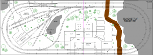
The first step in the rebuilding process was to come up with a new track plan. I found a very compact 4x8 plan online and made some slight edits to its design. I shared it here and quickly got some great feedback. I ended up acting on some of this feedback and also making executive decisions of my own to incorporate exactly what I wanted to accomplish with the layout. The 'final' track-plan is below. Track has been ordered and is waiting to be assembled. The table has been built (it's in two well-connected pieces, hence the center-line in the plan).

I'd like to consider the wiring for this project before I take any more steps. Unfortunately, I feel wiring is the area of model railroading I know least about. I think this may be due to my age; I'm currently 16. The last time we (my Dad and I) built a layout, I'm sure that both he and my grandfather simply did it and didn't involve me to a great extent (since I was young then (and now)).
I would strongly prefer to stick to DC, though I understand DCC is all the rage amongst experienced model railroaders. The reasoning for this is that doing so will enable me to use all of my locomotives. I have 5-6 DCC ready ones, and perhaps a dozen more that are high-quality and would warrant the effort to install a decoder. However, I have a few train-set quality (cheap plastic) locomotives that I still want to run AND that I could never justify spending money to put a decoder in. So it's DC and run these, or DCC and don't. Cost is also a factor, though I'm funding this whole project myself and can accept that my wallet will get thinner if I take any action other than stopping.
On my previous layout (the one that I tore down), we used a dual-throttle DC controller. The layout was, essentially, one loop inside another. Each throttle controlled one loop and thus any trains on it. Problems I encountered with this:
1) The loops were connected with two crossovers. We had insulated rail joiners to separate the current, but whenever a train would cross this line, it would jump (an instant increase or decrease in speed). The two loops didn't have the same amount of power.
2) Running a locomotive on the inner loop for an extended period of time would cause the power-pack to overload.
3) Running a locomotive on the inner loop would cause the lights to dim.
4) The re-used turnouts were AWFUL and made the whole thing unusable. No powered frogs.
As I mentioned above, I'm not familiar with how wiring works. However, I think the following things could have played a role in causing the above problems.
1) I believe we had the lights all wired to the inner-loop throttle, drawing current. This would certainly have had an effect, correct?
2) If you wire the power to the track unevenly, or have more track connected to one throttle (there was a branch off of the inner loop, connected to the inner-loop throttle), would this have an effect?
3) The power pack we had (still have) seems to be a quality pack. However, could problems like this be attributed to the pack's amperage (no idea what that unit means) limitations AND/OR a defect in the pack?
So all of those problems would have been very difficult to fix with less effort than it would take to start over. Which is why I'm starting over, but I'd like to get it right this time.
This new layout introduces some complications. Again, it's got two loops, and I'd like to be able to run trains at different speeds and going different directions on these loops. Further complicating things is the reversal track in the center. Again further complicating things is that I'd like to have wired frogs but don't know if this would affect anything on a large scale. As I said, have never wired before.

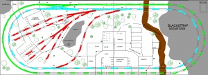
So here's the track plan again with three sections. I'd like to power each separately (connected to it's own throttle). I could match the power/track-length ratios of all three sections to hopefully avoid the jumping problem. I've been looking for a tri-throttle DC power pack. I did come across this (<-- link), which is a Model Rectifier Corporation Tri-Pack Model 2. It looks quite old, though, and old generally means bad. I'm not keen on turning the dials to approximately the same place just to match the speeds either. A digital display to match numbers, maybe (even though this almost certainly doesn't exist). Would anyone be knowledgeable about a newer system?
It's a bit of a unique need, I'm sure, so I doubt I'll be able to get all (or any) of what I want. Any thoughts would be appreciated, I'm really trying to figure out what the best way to approach this project is.
Thanks for reading my novel!
About six months ago, I tore down my old HO scale layout. It was a 4x8 built with the help of my Dad that never really worked. The track had been reused several times over (never a good idea, I learned) and we had made a bunch of rookie mistakes that, collectively, hindered operation. Rather than tear it up to fix LOTS of problems, I decided to rebuild.
The first step in the rebuilding process was to come up with a new track plan. I found a very compact 4x8 plan online and made some slight edits to its design. I shared it here and quickly got some great feedback. I ended up acting on some of this feedback and also making executive decisions of my own to incorporate exactly what I wanted to accomplish with the layout. The 'final' track-plan is below. Track has been ordered and is waiting to be assembled. The table has been built (it's in two well-connected pieces, hence the center-line in the plan).

I'd like to consider the wiring for this project before I take any more steps. Unfortunately, I feel wiring is the area of model railroading I know least about. I think this may be due to my age; I'm currently 16. The last time we (my Dad and I) built a layout, I'm sure that both he and my grandfather simply did it and didn't involve me to a great extent (since I was young then (and now)).
I would strongly prefer to stick to DC, though I understand DCC is all the rage amongst experienced model railroaders. The reasoning for this is that doing so will enable me to use all of my locomotives. I have 5-6 DCC ready ones, and perhaps a dozen more that are high-quality and would warrant the effort to install a decoder. However, I have a few train-set quality (cheap plastic) locomotives that I still want to run AND that I could never justify spending money to put a decoder in. So it's DC and run these, or DCC and don't. Cost is also a factor, though I'm funding this whole project myself and can accept that my wallet will get thinner if I take any action other than stopping.
On my previous layout (the one that I tore down), we used a dual-throttle DC controller. The layout was, essentially, one loop inside another. Each throttle controlled one loop and thus any trains on it. Problems I encountered with this:
1) The loops were connected with two crossovers. We had insulated rail joiners to separate the current, but whenever a train would cross this line, it would jump (an instant increase or decrease in speed). The two loops didn't have the same amount of power.
2) Running a locomotive on the inner loop for an extended period of time would cause the power-pack to overload.
3) Running a locomotive on the inner loop would cause the lights to dim.
4) The re-used turnouts were AWFUL and made the whole thing unusable. No powered frogs.
As I mentioned above, I'm not familiar with how wiring works. However, I think the following things could have played a role in causing the above problems.
1) I believe we had the lights all wired to the inner-loop throttle, drawing current. This would certainly have had an effect, correct?
2) If you wire the power to the track unevenly, or have more track connected to one throttle (there was a branch off of the inner loop, connected to the inner-loop throttle), would this have an effect?
3) The power pack we had (still have) seems to be a quality pack. However, could problems like this be attributed to the pack's amperage (no idea what that unit means) limitations AND/OR a defect in the pack?
So all of those problems would have been very difficult to fix with less effort than it would take to start over. Which is why I'm starting over, but I'd like to get it right this time.
This new layout introduces some complications. Again, it's got two loops, and I'd like to be able to run trains at different speeds and going different directions on these loops. Further complicating things is the reversal track in the center. Again further complicating things is that I'd like to have wired frogs but don't know if this would affect anything on a large scale. As I said, have never wired before.

So here's the track plan again with three sections. I'd like to power each separately (connected to it's own throttle). I could match the power/track-length ratios of all three sections to hopefully avoid the jumping problem. I've been looking for a tri-throttle DC power pack. I did come across this (<-- link), which is a Model Rectifier Corporation Tri-Pack Model 2. It looks quite old, though, and old generally means bad. I'm not keen on turning the dials to approximately the same place just to match the speeds either. A digital display to match numbers, maybe (even though this almost certainly doesn't exist). Would anyone be knowledgeable about a newer system?
It's a bit of a unique need, I'm sure, so I doubt I'll be able to get all (or any) of what I want. Any thoughts would be appreciated, I'm really trying to figure out what the best way to approach this project is.
Thanks for reading my novel!
Last edited by a moderator:

