
You are using an out of date browser. It may not display this or other websites correctly.
You should upgrade or use an alternative browser.
You should upgrade or use an alternative browser.
Tortise switch Machines and signals
- Thread starter CGW121
- Start date
Iron Horseman
Well-Known Member
It sort of depends on what you want the signal to tell you. Green for straight and yellow for diverging? And secondarily how have you wired the tortoise. And do the WeHonest signals already have resistors or not?I have some tortise switch machines that I would like to attach signals too. Does anyone know of accurate info on how to do this? A schematic
would be fine. These signals are 2 color green and yellow, and are made by WeHonest. 2 lights green and yelllow.
Mike
Here is one simple way assuming no pre-wired resistors in the signals. The motor becomes the resistor.
CGW121
Well-Known Member
The WeHonest signals are 3 wire green yellow and black I think I need 4 wire, or am I missing something.It sort of depends on what you want the signal to tell you. Green for straight and yellow for diverging? And secondarily how have you wired the tortoise. And do the WeHonest signals already have resistors or not?
Here is one simple way assuming no pre-wired resistors in the signals. The motor becomes the resistor.
View attachment 133320
Iron Horseman
Well-Known Member
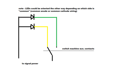
Not necessarily. Do you know which one is "common"? I would guess black, with yellow for yellow color and green for green color.The WeHonest signals are 3 wire green yellow and black I think I need 4 wire, or am I missing something.
That would give something like this.
CGW121
Well-Known Member
I will try this and get back to you.Not necessarily. Do you know which one is "common"? I would guess black, with yellow for yellow color and green for green color.
That would give something like this.
View attachment 133349
Mike
CambriaArea51
Well-Known Member
There should be how to wire signals in the paperwork with the tortoise.
The Tortise has a a DPDT switch in the contacts, so that's what you have to work with without adding any additional switches.
Generally, one side of the switch power supply would go to the common and then one side of the switch would go to one light and the other side would go to the other light. Which one depends on how the switch is lined and what lights you want to come on when.

Generally, one side of the switch power supply would go to the common and then one side of the switch would go to one light and the other side would go to the other light. Which one depends on how the switch is lined and what lights you want to come on when.
Last edited:
CGW121
Well-Known Member
Thanks DaveThe Tortise has a a DPDT switch in the contacts, so that's what you have to work with without adding any additional switches.
Generally, one side of the switch power supply would go to the common and then one side of the switch would go to one light and the other side would go to the other light. Which one depends on how the switch is lined and what lights you want to come on when.
View attachment 133393
I need a schematic, as I learn easier that way. Trouble with utube stuff is they they talk endlessly and if they have a drawing it is useless.
Mike
You will have to play with it to make sure you have all the positive and negative connections oriented correctly, so don't solder it together until you have tried it. You might also need a resistor on line with the LED's depending on your power source.
Since its a DPDT switch, the other contacts can power frogs or a second signal if you have two switches in line.
Since its a DPDT switch, the other contacts can power frogs or a second signal if you have two switches in line.
cv_acr
Well-Known Member
Not likely.Not necessarily. Do you know which one is "common"? I would guess black, with yellow for yellow color and green for green color.
That would give something like this.
View attachment 133349
The signal isn't going to be wired like that with the LEDs in opposite directions. When you've seen circuits like that, it's for wiring a SINGLE bi-polar bi-colour red/green LED, which will light red if power flows one way, or green in the other.
A signal with separate coloured LEDs in in, is going to have a common on one side, and all the LEDs facing the same way with an individual lead on each one, and relies on physically switching which wire is receiving power, not reversing the direction of the power flow.
So your circuit will only ever work on one of the lights, and the other won't light....
Attachments
CGW121
Well-Known Member
Which is the trouble I am having. Black wire is common. Green wire for green light. Yellow wire for yellow light.So your circuit will only ever work on one of the lights, and the other won't light....
Mike
Iron Horseman
Well-Known Member
Yup, you are exactly right, I am too used to having independent LEDs to work with. Sorry CGW121 I lead you astray.The signal isn't going to be wired like that with the LEDs in opposite directions. When you've seen circuits like that, it's for wiring a SINGLE bi-polar bi-colour red/green LED, which will light red if power flows one way, or green in the other.
Rico
BN Modeller
Which product are you talking about, can you post a picture?
I think I might have an idea.
I’m looking at these ones, also from Wehonest:

These are red/green/yellow with a common.
This arrangement will require selecting one of three routes for power.
I usually use bi-color LEDs which require reversing polarity as inline with a tortoise.
I think I might have an idea.
I’m looking at these ones, also from Wehonest:
These are red/green/yellow with a common.
This arrangement will require selecting one of three routes for power.
I usually use bi-color LEDs which require reversing polarity as inline with a tortoise.
Last edited:
