Power Needs for Complex Layouts


johnmiller

New Member
I am planning a Kato N-Scale layout. My current plan is to use what I have purchased so far, the M1 Kato Master 1 Set, which has the Basic Oval and Power Pack; the V1 Kato Variation Mainline Siding Passing Set; plus the V6 Kato Outer Loop Set, which I want to purchase.

Illustrations of how the sets can be combined are here:

http://katousa.com/cgi-bin/dl/dl.pl?dl.mif,Layout-Plans.pdf

Towards the top right of the .pdf is the M1 Master Set + V6 Outside Loop example. I guess, just imagine the siding added on to that!

So, here's my question: All this combined track would more than double the original amount of track of the M1 set. Now, I would think that, as long as I don't put in a cross-over section, or join the two ovals in any other way, they would be independent. I would need two power packs, one for each oval.

But, if I did join them using a cross-over, etc., am I right that they would be one unit? And if that's the case, I would wonder if the one power pack would have enough juice to power the combined layout. If not, or if I wanted more power, how do I do that? Is there a booster power pack? Or, some other solution?

I would think that extra power is needed when the amount of track reaches some approximate point. I don't know if my layout would, but I am guessing there are certainly those that do!

Thank you very much for your time and assistance! I appreciate it.
 
John,

You didn't say how many trains you would be trying to run. One power pack should be sufficient if you are only trying to run one train. You would need to add some additional feeders aournd the layout in any areas where the train runs slowly or not at all. Also be careful of creating a reverse loop(s) as these need special wiring in DC.

It would be helpful to see a track plan for the layout you are going to build.

Glenn
 
Hi John -

As Glenn suggests, it will be the wiring and not the power pack that limits performance. If you feed power to the tracks at only a single point, the part of the layout farthest from the power pack will have the largest drop in voltage. That's where a loco is most likely to slow down.

However, if you run bus wires around the layout and attach feeders at regular intervals, every part of the layout will receive approximately the same voltage, and so performance will be consistent across the whole layout. By using sufficiently heavy gauge bus wires -- even 16 gauge will be large enough for the layout you describe -- you minimize the resistance and therefore the voltage drop, but it is equally essential to have enough feeders.

You will find various "rules of thumb" regarding feeders. You might try a set of feeders every 6 feet, which would mean about 4 sets of feeders for that layout. I'd probably connect feeders in the middle of the front and rear straights on both loops. In the unlikely event that there are places where trains slow down due to low voltage, you can always add more feeders. If you keep the feeders short -- less than 12 inches -- the wire gauge for the feeders can be fairly small: 18 to 22 gauge.

Good luck,

- Jeff
 
As stated above, the power should be fine it is the feeders that will help provide smooth and continuous running of your trains. As a rule, I always drop a feeder for every piece of flex track I use which is about every 3 feet regardless of scale. With the size layout you are going for, every 5-6 feet should probably do the trick for you.
 
All very good advice. The only caveat goes back to how many trains you're planning to run at one time. If you're just using DC and want to run two trains you'll need to keep the two ovals isolated electrically from each other and use two power packs. That doesn't mean you can't have a crossover, but it will have to have insulated rail joiners to keep the two ovals from connecting.

If you ARE just going to run ONE train, one power pack is more than enough for that layout. Though could I suggest that for only one train the Master1+V9 layout might be a better thing to use? That gives you twice the continuous run for the same amount of space with a more pleasing look to it than running one train on just the two ovals. From the looks of it, converting to that from what you have now wouldn't entail much more than buying a 45-degree crossing and possible an odd piece of track or two. Just a thought.
 
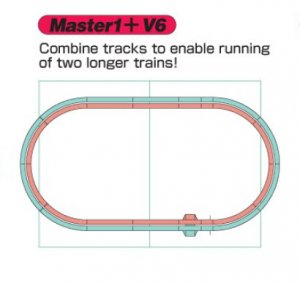
Here is basically what I am trying to build:

Kato M1 + V6.jpg

It is the Kato M1 Master Set + the Kato V6 Outer Loop Variation Set.

I have the V1 Siding Set, and a Three-Color Signal, but I would putting both of those on the M1 Inner Loop. I was wondering about what I would need power-wise, since I would have two independent loops. I would like to run two trains at once. The workspace I have available is 5 feet by 3 feet.

I called Kato USA today, and here is what I was told:

The two loops would be independent. As long as they are not connected by a crossover, etc., you would need two Power Packs, one for each loop. As has been mentioned in this thread, if the two loops were connected, I would need to make electrical considerations if I have more than one power input.

I might get two Power Packs to start off with, so I can run the two loops as I would like. Otherwise, if I were to connect the loops, I would go DCC and get DCC locomotives to run on the layout.

By the way, Kato USA is very helpful! No phone system you have to go through to get to someone. So, he said that the rule of thumb in regards to power is you supplement power every 10 to 12 feet of track. So, all of you and Kato are in agreement on that!

When it comes to feeding different parts of a loop, that is where I still have questions. How is that done? Are you using a splitter of some kind? Do you feed the power output from your Power Pack into a device that then splits the power into multiple outputs? And, you then run the cable from your feeder pieces into that device?

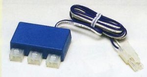
Here is a Kato component that seems to fit that purpose, the Kato #24-827 N scale 3-Way Extension Cord, 35":

Kato 24-827 Power Splitter 02.jpg

Would this work for distributing power to different parts of a loop? I would guess that I would plug the cord into the Power Pack. Then, I would plug each of the feeders into one of the three connectors. Also, would that create any electrical issue? Or, since this is one source being distributed, would that mean no electrical issues since they all come from the same source?

Again, thanks to everyone for your help with these questions! I really appreciate it!
 
Hi John -

I don't use Unitrack myself, but I think you can distribute power to the various parts of the layout using Terminal Unijoiners connected to 3-Way Extension Cords. Hopefully, someone with Unitrack experience can confirm my supposition.

The Unitrack power distribution accessories all appear to be polarized, meaning a plug can be inserted into a socket in only one way. This should prevent incorrect wiring connections, or at least minimize the possibility. Human error is always possible!

- Jeff
 
Thank you for the reply, Jeff! It seems to me that the 3-way plug I found is what you are thinking of when it comes to distributing power. I will consult with Kato and make sure I have the right component in mind!

I appreciate your help, and the help of everyone else! I will follow all of your advice, and incorporate a strategy for distributing power on my layout.
 
John: I recommend that even with using DC to start, make sure that any engines you get are DCC ready. Whether Kato or others, then if you want the benefits of DCC at least you will not need to buy new engines.
 
I have the V1 Siding Set, and a Three-Color Signal, but I would putting both of those on the M1 Inner Loop. I was wondering about what I would need power-wise, since I would have two independent loops. I would like to run two trains at once. The workspace I have available is 5 feet by 3 feet.

John, FYI. If you do go with DCC at a later date, you'll have to lose the signal. There was a thread about a mysterious short on a Kato unitrack layout that couldn't be found, until the product technical information for the signal was read. It is not DCC compatible and will cause a short. I've done a search to try to find it but no luck. It's been within the past year IIRC.


Back
Top