I made the leap and purchased what I thought I needed but can’t figure out how to hook up power to track section (kit has 7 terminal tracks) and turnouts ( kit has 8). I have the Atlas “Dispatcher’s Delight” layout HO-2 (HO SCALE code 83) and the Digitrax Zephyr Express DCC controller. Each terminal section, rail A connects to each selector on the Atlas #215 selector, but where do the common rail wires connect to? Also, where do you connect the #215 connector to power on the Zephyr? Then I have the Atlas #584 switch controller for the turnouts, it has three wires that connect the turnout to the control box, but how do you connect it to the Zephyr? Once all that is tied in and has power, will the Zephyr control the terminal tracks and turnout or do I still use the switches? Hope someone can help, I have watched every YouTube video and read the manuals but can’t figure this out. Thanks in advance.

You are using an out of date browser. It may not display this or other websites correctly.
You should upgrade or use an alternative browser.
You should upgrade or use an alternative browser.
New and lost
- Thread starter Catfish
- Start date

santafewillie
Same Ol' Buzzard
Welcome to the forum. I cannot answer all of your questions presently until I look some of this stuff up. But I can say that there is most likely no way that you need 7 terminal tracks. You can still use them for straight sections without connecting power. It would help to get more definitive answers if you indicated the size and potential shape of your layout, oval, point to point, folded dogbone etc. Someone else who is more familiar with the Zephyr Express controller could tell you if it has AC or DC terminals for the switches. You're correct regarding "rail A" connecting to the selector, "rail B" or common rail wires would all be connected to the the other terminal on a power pack. But with DCC powering the layout, selectors are totally unnecessary. You just need a pair of buss wires connected to the track.
Atlas #584's are only for LH switches and requires a companion #56 to activate the #584 and attached switch. If you have RH switches, you need #585. You also posted #215 Connector. #215 is a selector, a Connector is #205. While both could be used on a DCC layout, that use would be limited and a #205 Connector would be more appropriate.
Atlas #584's are only for LH switches and requires a companion #56 to activate the #584 and attached switch. If you have RH switches, you need #585. You also posted #215 Connector. #215 is a selector, a Connector is #205. While both could be used on a DCC layout, that use would be limited and a #205 Connector would be more appropriate.
You will need to connect Track A on the Zephyr to one terminal connector on the layout, and Track B to the other. As long as you connect them so Track A is to one rail, and Track B to the other rail, that will be what you need.
You will need to purchase a decoder and motor, if the turnout doesn't have a motor, for every turnout you want the Zephyr to control.
Operating the turnouts will be through the "SW" button on your Zephyr.
You will need to purchase a decoder and motor, if the turnout doesn't have a motor, for every turnout you want the Zephyr to control.
Operating the turnouts will be through the "SW" button on your Zephyr.
Thanks for info, I am still confused how the Zepher powers the turnouts and terminals through the switches. I finished wiring all turn outs and connected to switches, top row of switches in picture and I have all the terminal sections of track wired and hanging down. I attached a picture of where I am at now. If each terminal has two wires, one wire would go into each switch and the other wire connect to the common rail wire. Then maybe I run a wire from the Zepher Rail A to the switch and run a wire from Zepher Rail B to the common wire split and to the switch. That may work, will try that, but then how do I connect the Zepher to the turnout switches?
Attachments
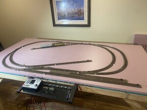
Looking at the Digitrax literature it doesn't look like there is provision to power the turnout switches (the 7 in the upper right of your control panel). You will need to provide an external power source for these. Electronic shops like Radio Shack provide a variety of power bricks that plug into the wall. The packaging of the switches should tell you what power input you need. I suspect that it will be some form of AC. With DCC, as mentioned above, you don't need block detection, so you don't need to wire in the two 4-switch units (green switches, Atlas #215 selector). For basic operations you will need to connect "Rail A" and "Rail B" to alternate sides of the track - you can use a single terminal track, or joiner connectors (have wires attached to the rail joiners that can be used for connections, or solder leads to the outside of the rails.
Edit: for an external power source, this image shows 15-18V AC input required: http://3.bp.blogspot.com/-XZs4nrzNg...s/2SxQTV7boFM/s1600/Switch-Machine-Wiring.jpg (also is a pretty good overall wiring diagram for these switches). Potential power supply, would just need to cut the barrel plug off and split the wires: https://www.amazon.com/18VAC-Wall-Adapter-Power-Supply/dp/B00E4WKH2Q
One final note: with the equipment that you have you will NOT be able to control the switches through the Digitrax controller. There are additional DCC components that will enable this.
Last edited:
Thank you for the detailed response, very helpful, finally got power and running the train but cars kept derailing, I took the whole thing apart, cut wires and pretty much got aggravated, come to find out, the Atlas railroad kit has three sections of 15” turn sections and in the back of the guide it says most engines and cars can not run on 15” turns, so now I put it all back together but need to figure out what to do about the one turn that is to sharp, and rewire the darn thing for power.
Looking at the Digitrax literature it doesn't look like there is provision to power the turnout switches (the 7 in the upper right of your control panel). You will need to provide an external power source for these. Electronic shops like Radio Shack provide a variety of power bricks that plug into the wall. The packaging of the switches should tell you what power input you need. I suspect that it will be some form of AC. With DCC, as mentioned above, you don't need block detection, so you don't need to wire in the two 4-switch units (green switches, Atlas #215 selector). For basic operations you will need to connect "Rail A" and "Rail B" to alternate sides of the track - you can use a single terminal track, or joiner connectors (have wires attached to the rail joiners that can be used for connections, or solder leads to the outside of the rails.
Edit: for an external power source, this image shows 15-18V AC input required: http://3.bp.blogspot.com/-XZs4nrzNg...s/2SxQTV7boFM/s1600/Switch-Machine-Wiring.jpg (also is a pretty good overall wiring diagram for these switches). Potential power supply, would just need to cut the barrel plug off and split the wires: https://www.amazon.com/18VAC-Wall-Adapter-Power-Supply/dp/B00E4WKH2Q
One final note: with the equipment that you have you will NOT be able to control the switches through the Digitrax controller. There are additional DCC components that will enable this.
Thank you for the detailed response, very helpful, finally got power and running the train but cars kept derailing, I took the whole thing apart, cut wires and pretty much got aggravated, come to find out, the Atlas railroad kit has three sections of 15” turn sections and in the back of the guide it says most engines and cars can not run on 15” turns, so now I put it all back together but need to figure out what to do about the one turn that is to sharp, and rewire the darn thing for power.
Yah, 15" radius curves are only going to accommodate the shortest of locomotives. It can be very frustrating at first, but also very rewarding. Patience, planning, adaptability, and patience are key (yes, patience is twice because you need a lot sometimes
") ).
).I made the leap and purchased what I thought I needed but can’t figure out how to hook up power to track section (kit has 7 terminal tracks) and turnouts ( kit has 8). I have the Atlas “Dispatcher’s Delight” layout HO-2 (HO SCALE code 83) and the Digitrax Zephyr Express DCC controller. Each terminal section, rail A connects to each selector on the Atlas #215 selector, but where do the common rail wires connect to?
It sounds like you are using a DC wiring plan for a DCC layout. If you are going to use DCC to run your trains, then you don't need the "selectors", that's for DC operation (using a power pack instead of a Zephyr).
If you are using DCC connect all the left terminals together and then wire all the right terminals together and then connect those to the Zephyr. There should be a connection on the Zephyr labeled "To Track" or "output" or something like that.
Short answer is you don't.Then I have the Atlas #584 switch controller for the turnouts, it has three wires that connect the turnout to the control box, but how do you connect it to the Zephyr?
You don't power the switches using the Zephyr. you can use an old power pack or 12 volt wall wart transformer to power the switches.
For each turnout there are three wires, one is a common and the other two are "normal" and "reverse" (normal being the straight route).
All the commons get connected together. The other two wires go to a momentary push button switch, one for each wire. Atlas sells a switch controller. On the push buttons, one side is connected to the switch solenoid and the other side is connected to the power source. Nothing is connected to the Zephyr.
If you want to control the switches using the Zephyr, then it gets more complicated. Every switch needs a "stationary decoder" The stationary decoders all are connected to the Zephyr on one side and the switch solenoid on the the other.
If you want to control the switches using the Zephyr, then it gets more complicated. Every switch needs a "stationary decoder" The stationary decoders all are connected to the Zephyr on one side and the switch solenoid on the the other.
IF you go this route you'll want the DigiTrax DS64 Quad Stationary Decoder. It is powered by it's own 12VDC wall wart (there is the option to power it from the Zephyr, but I don't recommend that). It controls four turnouts and is connected to the Zephyr via DigiTrax "LocoNet". The only "programming" you have to do is:
1) Assign each switch an address. From the factory they're addressed 1-4. Additional units will need to be changed to 5-8, 9-12 and so on.
2) Set the type of turnout each address is controlling: Slow motion/stall or solenoid/momentary. They're set to the latter from the factory, but should be checked just to be certain. If they're set to slow motion/stall it'll burn up Atlas switches.
https://www.digitrax.com/media/apps/products/stationary-decoders/ds64/documents/DS64_flattened.pdf
Thanks for all this great information. my Atlas track kit has two 15” curves and two 18” curves, my cars derail on the 15” because the back end of the loco pushes past the track and pulls the cars off. Much reading and now I know 15” is bad for my size loco and cars. Without scrapping the whole set and starting over, is there a way to redesign the layout to convert the 15” turns to 18” and remain on the 4x8 sheet? I purchased a variety of size track and some 36” flex track. Pic of track and pic from plan attached for ref.


santafewillie
Same Ol' Buzzard
An alternative to rebuilding (at least temporarily) would be to install Kadee # 26 or #146 long shank couplers to the engine and the car immediately behind it. That will give them a bit more swing. It may or may not be enough to prevent derailing on 15" curves though.
Looking at the track plan... the inside loop on the right is half of a 36" circle, so that's an 18" radius.
It looks like the 18" & 15" measurements on the plan are the length of the rigid track sections (as are the 1" & 6").
Most locos and rolling stock with three axle trucks specify: Minimum radius 18", recommended 22"
It looks like the 18" & 15" measurements on the plan are the length of the rigid track sections (as are the 1" & 6").
Most locos and rolling stock with three axle trucks specify: Minimum radius 18", recommended 22"
2) Set the type of turnout each address is controlling: Slow motion/stall or solenoid/momentary. They're set to the latter from the factory, but should be checked just to be certain. If they're set to slow motion/stall it'll burn up Atlas switches.
Correction: You can't set the type of turnout for each address. Each DS64 controls either all stall type switches or all momentary.
Okay, I am going a complete other direction, pic attached of new plan using AnyRail software. Dedicating room to layout, only using 28” curves. Initial design attached (boxes represent 1 ft ) but sure will take a long time to build everything but want to get the continuous loop in soon. I plan to use a lot of Atlas Code 83 flex track and use Peco turnouts. I am unsure which Pleco # turnout is closest to my broad radius turns (I think #8 but don’t understand what their numbering system means) Before I start construction (the second time) would love you all’s thoughts on this concept. I still plan to use the Zepher Express to control but know I may need other add ons for more power and to run the turnouts. I have been reading lots on the different types of Peco turnouts and am a little confused, insulated, uninsulated, uni and then the additional motor to run them and turtles, ect). Thank you all for your feedback, I know I am learning a lot the hard way but it is great to be able to reach out to those that have been here before and hopefully prevent me from losing more money and time, but those mistakes so far have taught me a lot. Merry Christmas to you.
 I have four engines so far. The room I am using for the U will be 6’x16’’19’x16’x6’.
If you're going to use PECO turnouts then I would go with PECO flex track also because Atlas & PECO rails are different, so the rail joiners are different. While PECO turnouts are more expensive - and justifiably so IMO - flex track is about the same $, so shop around.
For the turnouts: On the PECO site all of the details about the turnouts are listed. I assume AnyRail, like SCARM, allows you to pick the turnouts by the manufacturer part number, so just pick the turnouts that work for your track plan. I don't see any reason not to go with the insulfrog.

 peco-uk.com
For your track plan pictured:
I would put a passing siding on the far right between the two mainline tracks. Make it as long as you possibly can. I have two on my layout and they're both too short.
The spurs on the left I would make 3' longer and see if I could work a third in there. That would give you some semblance of a yard.
I would also add some spurs elsewhere for servicing industries and whatnot. When I started planning I put the "features" in first, then planned the track. The coal mine goes here, the town goes here, the industrial district goes here, etc.... then I "laid" track. Of course there was a lot of moving around and adjusting to account for turn radii and grade changes, but it was all digital so all that was spent was time.
You might consider putting some more bump-outs (like where your roundhouse is) on the sides for those spurs and industries.
I assume the white blocks in the center of the loops are so you can duck-under-pop-up for maintenance. I have two of those also that I used a LOT while building and landscaping. But once done I put in a removable "plug" of pink foam then landscaped it in. My town sits on top of one and my farm is on the other. Granted, the plug will only need to be removed in the event of an "emergency", and will require some landscape repair if I ever do have to pull it, so I made sure the trackwork that I can't reach with it in place is rock-solid.
For the turnouts: On the PECO site all of the details about the turnouts are listed. I assume AnyRail, like SCARM, allows you to pick the turnouts by the manufacturer part number, so just pick the turnouts that work for your track plan. I don't see any reason not to go with the insulfrog.
Track
Browse and build your wishlist from the entire range of products, including PECO, Ratio, Wills, Modelscene and K&M Trees.
peco-uk.com
For your track plan pictured:
I would put a passing siding on the far right between the two mainline tracks. Make it as long as you possibly can. I have two on my layout and they're both too short.
The spurs on the left I would make 3' longer and see if I could work a third in there. That would give you some semblance of a yard.
I would also add some spurs elsewhere for servicing industries and whatnot. When I started planning I put the "features" in first, then planned the track. The coal mine goes here, the town goes here, the industrial district goes here, etc.... then I "laid" track. Of course there was a lot of moving around and adjusting to account for turn radii and grade changes, but it was all digital so all that was spent was time.
You might consider putting some more bump-outs (like where your roundhouse is) on the sides for those spurs and industries.
I assume the white blocks in the center of the loops are so you can duck-under-pop-up for maintenance. I have two of those also that I used a LOT while building and landscaping. But once done I put in a removable "plug" of pink foam then landscaped it in. My town sits on top of one and my farm is on the other. Granted, the plug will only need to be removed in the event of an "emergency", and will require some landscape repair if I ever do have to pull it, so I made sure the trackwork that I can't reach with it in place is rock-solid.
Stumpy, made some modifications based on your advice, thank you, I will add more later as I progress. I went with Peco track all around, 61 sections of 36”, Peco SL 8381 and 8382 #8 switches. I am not sure what to order to motorize and hook to the ZepherExpress? Also read a lot of bad reviews on turn tables, open to any recommendations. Thanks again.

Last edited:
