New All Around - Grade?


Stadawim

New Member
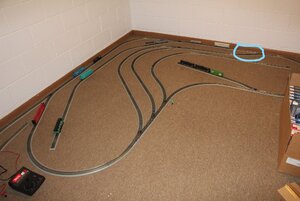
Hey peeps. Just bought a house, and i get a train room (the Boss even helped find the house that had one).

So i'm setting up possibilities, and this is one i'm stuck on for now. I kinda like it, other than it's a little deep to the back curve. I believe it has enough splits and ends to do what i'd like it to do, but i wanted to get some of you old pros' thoughts on it.
Please keep in mind this will be my first real layout - my previous 5 have been two ovals, a circle, a figure 8 and an elevated oval.
So some details: The room is about 11' x 11'. The 'back' wall as you see in the shot on the left is a full 11', the side wall at the top is just under 11'.
This layout is done with Bachmann NS EZ Track (if it isn't obvious). Will i keep it on the layout when it's finished? Who knows? It's what i have the most of, and it works.
It's on the floor so i can prep the table of course. It's not staying down there! I know better. But i've been doing the testing down there.
Will i use that MRC200 Tech 4 in the pic? Again, i dunno. One of the main reasons i'm doing this post is for this issue....

Which is i can't get power to it. I tested the outlet, and it's good. I think the MRC is a transformer, right? So that's okay to use, yes? But i can't even get my tester loco to move. That's the BN F2-A visible on the left. It's the el cheapo Model Power loco, so i don't particularly care what happens to it. And i know, i have been reading that bigger layouts need boosters. Didn't think this one was big enough yet. Well... I suppose it is. That's a lot of track. But i can't even get the loco to move over the power relay track.

So can i get some advice? Does the layout look good? I mean, nothing too strenuous for a consist or anything? Again, i think it does what i'm gonna want it to. What am i missing or messing up with the power? It's something obvious isn't it? Like i'm draining too much. But how does one do boosters? I've seen videos, and have heard about battery options (car/laptop/mobile). But the MRC was working fine in my previous abode. So i suspect the outlet. Or should i say, outlets. I have tried a couple down here (i'm in the basement of course). And the three do the same thing. So perhaps it's the wrong transformer for the layout?

I dunno. I'll take what i can get.
IMG_7146.JPG
 
Is this the first time you tried to run this layout with the controller? If so, you have a loop back at the top that will cause a DC short. Disconnect the straight that is going to the switch in the upper right and I bet it works.
 
Agreed, the two inner tracks that are curved and nested, all meet and then return to the one turnout that diverges off the main. That is a 'reversing loop' in two ways: it reverses the trains back the other way when they exit the loop, but they also reverse the polarity as soon as the first metal locomotive tire crosses over the frog. The polarity of the two rails has switched because what was left rail going away from the main track has looped back and is now the right rail. Conflict in polarity in DC. In DCC, it's actually a 'phase' conflict.

The remedy, if you would like to use the layout configured as you have it, is to control those two inner looped tracks by, first, gapping the two rails coming off the first turnout at the main, and then gapping both rails at the turnout where the long red car is at left. Then, you power all those inner rails by either a DPDT that reverses the polarity, or a Digital Reverser, either one, in series to a pair of heavier feeders coming off your power source.
 
So is the reach to the far corner more than 30 inches? It looks it but that could be camera angle throwing me off. As pointed out there is a definitely two return loops that will cause a short circuit.
 
Last edited:
I have a elevated work platform similar to the one shown in the first illustration in Jim 68cuda thread sold by Micro-Mark. It's called the Topside Creeper. I have spots on my layout that I will need to the platform to do ballasting and track work should certain turnouts give me problems. I purchased the platform when it was on sale and have not used it since my purchase several years ago, but I know that it will come in handle when the ballast projects begin and or the need to reach a troublesome turnout.

The platform is well made but heavy due to its design to hold the modelers weight while working. Some assembly is required.

Even with these platform "tools" I would recommend avoiding layout designs that require a long reach to construct and maintain a model railroad.

1598476761691.png

Here's a photo taken of the Topside Creeper from Micro-Mark's web site.

Greg

##################
 
Is this the first time you tried to run this layout with the controller? If so, you have a loop back at the top that will cause a DC short. Disconnect the straight that is going to the switch in the upper right and I bet it works.
So you guys are saying this one is the culprit? Leading to that inner section. I admit it did look sketchy.
So is the reach to the far corner more than 30 inches? It looks it but that could be camera angle throwing me off
It is indeed. The left loop is about 50" from wall to inside, while the top loop is about 40".

Whoa. There's an elevated stand-like diving board looking thing for this?!? Okay. I may either have to trim some width or get real serious here.
 

Attachments

  • InkedIMG_7146_LI.jpg
    InkedIMG_7146_LI.jpg
    511.1 KB · Views: 131
Yes, that's exactly the spot I'm talking about. If you trace the outside rail through that crossover back to the other end, you'll find that it ends up on the inside of your outer loop. This is what's causing your short, resulting in the track not working. Again, to prove it out, disconnect the track from the inside crossover that connects to that switch (not on the outer loop) you should be able to run trains.
 
Whoa. There's an elevated stand-like diving board looking thing for this?!? Okay. I may either have to trim some width or get real serious here.

Your other option would be a lft out section or two that would allow you to duck under the layout and come up in the middle to access areas along the wall. You will probably still need to make some adjustments to the track plan to allow for the openings in the surface of the layout.
 
Lift outs aren't hard to do. I have 2 of them in my layout as my knees are too shot to duck under.
 
You CAN use your track plan, but it will require some consideration for the short, and also for the excessive reach. Generally, most of us prefer the layout's main operating surface, on which most of the track will be, to be about chest high. It makes the view much more interesting and natural, and it makes working below (all that wiring) so much easier. Unfortunately, with that increased height comes a reach problem, particularly with elbows that want to sweep away trees, buildings, power poles, switch stands, and tumble rolling stock nearby. You'll need a footstool at the very least. Murphy says you'll have the most fixing to do at the furthest reaches, so get used to hauling a footstool or an overhead creeper over to where the trouble is.
 
I agree that you have a reversing loop which is causing the short circuit. You might want to consider redesigning your layout into a "folded dogbone"with the part that is closest to the corner of the room narrowing. I would expect you could find plans in one of the layout design books. Although my layout room is 14' x 14', the presence of a window that can't be blocked (local fire regulations), and access to one of the loops (NOT reversing, just the track curving around similar to yours. has reduced mine to an 11' x 14' x 11' with a peninsula projecting out into the center of the room for the other loop and a large yard inside the main.
 
Congrats on your new home! We all started somewhere....as you can see the gang here has provided a lot of input. I would look at some these guys around the room layouts. There is a lot of talent here. Avoid having to reach more than 30 inches across the layout if you can. The 11x11 room is a good room size to work with. My temp layout is approximately 10 by 16. I did a around the room style with (2) duck under "holes" in the center but I am planning a lift out for one section to get to one of the "holes". You can look at my progress here....I am not an expert but again it is temporary and I am using this layout as a "practice" run until my garage addition is built. So it all just experimentation for me.


I am sure you will do well as you dive into your design. We are all here to help ya! Good Luck and just have fun!
 
The dog-boning or peninsula alterations are more intriguing. I'll probably change to suit one of those. There's also another portion of this run i didn't include. Just off the left side of the shot is a half-wall jutting out into the room. I will probably leave it there (for aesthetics, stability, etc) but cut a large enough hole to run track through because my hobby section is on the other side. This will be the 'shop'. All cleaning, repair and painting will be done on a spur on this side of that wall. You can just make out that's where the single run out to the left is illustrating. The section of track just visible by the center-beam car is the spur deconstructed for measurement purposes.
To answer a previous question i missed - no, up to this point it had not run anything yet. Well, cause of the power problem.
 
So you guys are saying this one is the culprit? Leading to that inner section. I admit it did look sketchy.

Oh yeah, any track that can result in the train reversing direction needs to be isolated and wired correctly with a switch to reverse the electrical polarity. Otherwise the "north" and "south" rails end up meeting each other and your whole layout is in a dead short. Nothing will work when there's a short circuit.


Back
Top