LED bleed through


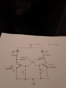
I'm attempting to build a flip flop circuit to indicate position of remote turnout switch to siding. This circuit works great except the 3 volt leds I'm using bleed through when not powered. I'm not sure how to stop the bleeding.
 

Attachments

  • 20200125_131522.jpg
    20200125_131522.jpg
    72.1 KB · Views: 224
You left out the capacitors.
Your circuit will always allow current through the LED.
base to emitter is basically a diode. So the left LED is in series with the right 'diode' completing a path for current.
Increasing resistor does not help since it cannot drop voltage until current flows, so it appears as a short for the nanosecond after DC voltage is applied.

http://www.talkingelectronics.com/projects/5-Projects/Projects16.html
 
Putting the LEDS aside. How is the switch thrown, by hand, with a tortoise, etc. I have about 10 tortoises with LED indicators attached a they work fine. I light the LEDS with the tortoise's internal switches # 345 / 567.

George
 
Putting the LEDS aside. How is the switch thrown, by hand, with a tortoise, etc. I have about 10 tortoises with LED indicators attached a they work fine. I light the LEDS with the tortoise's internal switches # 345 / 567.

George
That sounds great. However I have to use Atlas snap switches. I built my benchwork using 1-3/8" thick solid core oak doors with 2" foam board glued on top, making my total thickness of 3-3/8", which the wires with the tortoise are too short.
 
which the wires with the tortoise are too short.

I'm not sure what you mean? Then solder on longer wires. The wires I soldered to the tortoise internal switches are a least 12'' long maybe longer depending on where I have the LEDS positioned. George

tortosie_internal_switch_1.jpg
 
The wire I am referring to is the actuation wire from the tortoise to the snap switch, not the electrical wires.

But what's that have to do with the LEDS. Their on their own circuit. In the above photo the yellow wire is on one side of the circuit and the red and green the other. So when the switch is thrown the red LED is lit and when it's reversed the green LED is lit. No Flip Flop needed. Post a photo of your setup.
George
 
Traingeek344- I've been studying your diagram for the past few days and figured out what is going on. Like dennis461 said, current is traveling throught the "off" LED to the base-emiter of the transistor to complete the circuit. The simplest way to fix this circuit is to allow current to bypass the off LED and keep the voltage below 3V. I don't have a sketch to snap a phot of, so I'll try to describe the changes.

First- add a resistor of 1.6K ohms in parallel to the LED and 470 resistor.

Second- reduce the resistence of the 7.5k resistors to 5.6k ohms.

That should hopefully not change the operation of the circuit and keep the off LED OFF.

p.s. I'm assuming the coils for the switch are not part of this circuit.


Back
Top