Layout Room EntranceWay Bridges


Swing Out configuration?

I briefly considered such an arrangement prior to settling on the drop down one I am now building.

1) I was unconvinced in the dimensional stability to get all 3 levels of track to line up perfectly with this arrange attached to the door of the shed.

2) I did NOT want the sole ability to run trains around the layout be confined to ONLY when the door was closed.
 
Upper level now to be double tracked.

I will be putting a double track bridge on that upper level instead of the single track one:
1) The single track one I had would not carrying very tall auto cars, nor double stack container cars, both of which need to run on that upper level. Bridge is on its way.
2) I can now run a train continuously around the upper level while another comes up or goes down the helix. Its going to require a little modifications to my refinery scene and my helium & cryogenic tracks, but I think i have a plan for that.
 
Bridge Selections
1) No need to select a bridge type for the lower staging level,...just plain plywood deck crossing.

2) I was originally hoping to fit in some sort of bascule bridge type, but almost no one made a double track one. I did consider 2 side-by-side Walthers ones, but the arrangement was too wide and would have interfered with both my blast furnace on one side, and the waterfront scene on the other side. So reluctantly I sold off my Walthers kits and decided to use the Walthers double track swing bridge.
3) I thought perhaps the use of this relatively simple double track bridge was going to make life much simpler. Au contraire, going to have to consider a number of other installation problems,...just to name 2,...height above water surface already set by next door waterfront scene, and seriously considering restricting bridge to NO rotation as this would involve more cuts in the rails crossing the door opening in addition to those needed for the lifting structure,..too many cuts to align.

Nobody said this was going to be simple, straight forward.


And if this wasn't enough, I discovered that the long wooden single track bridge I had been thinking of using for the very top level,...well it won't accommodate dble-stacks, nor auto cars,...both of which I had planned on running up there on occasions.


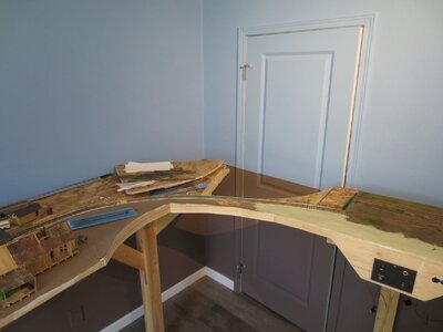
New top deck double-track bridge installation.

I am attempting a rather unique application of a long length of bridge rail,... in combination with sections of re-railers at either end. ( I am a real believer in having rerailers on either side of my elevated bridge rails crossing my entrance-way)

My bridge structure by itself does NOT span the entire width of the lifting section,..but rather there are two short sections of plywood deck on either end before the actual cut-off gaps. Those cut-off lines are illustrated here,..
DSCF8147, with cutoff line.jpg DSCF8148, with cutoff line.jpg
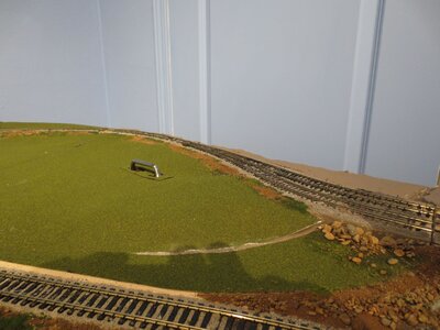
As you can see there is approx a 6" space between the end of the bridge tracks and the cut-off gaps. I want one half of the rerailer in that space (the other half will be on the other side of that cut-off gap).

I wanted to see if I could install that short piece of rerailer WITHOUT using any kind of rail jointer between it and the actual bridge tracks,....just make it one continuous track section. This involved removing the rails from the Atlas rerailers, then sliding those onto the ends of the extended bridge rails. This was quite an operation! In the photos above you will see I have done one side, and today hope to finish the other side.
 
I got my third level bridge installed !! Now to wire it up and run some trains around my top deck !! YAHOO

Pics still show a fair amount of construction going on, but amazingly the tracks on ALL 3 decks line up when the bridge is lowered in to place.
DSCF8152.jpg DSCF8153.jpg DSCF8154.jpg DSCF8155.jpg


Looking down from the top you can see the 3 different angled gaps of the tracks as they leave their respective decks to venture onto the tracks of the lifting structure.DSCF8156.jpg
 
Getting 404's on some of your photos/drawings. FWIW.

I can usually see photos here, so it might be something at your end? Or it could just be me.
The last group show up fine, so can see the basic idea, I think. Without motorizing the three lifts to raise with one press of the button, I think you would want three separate systems. However, you might also try connecting the two bottom bridges to the highest (powered) bridge with drop cables at the unhinged ends of all three. Maybe turnbuckle adjustments to get them all spaced just right. Or just close enough to work.

I would avoid using bungee cord :D lest you fling several trains, and HO figures too across the room and into the wall....

All that (general nonsense) said it's looking good,
 
Last edited:
Is anyone else having that problem with the photos? I can see them just fine.

BTW there is NO motorization of any of this bridge structure. All 3 bridges are mounted to the same wing-up frame that is raised by hand and clipped to the ceiling when taken from the entranceway. ( I had been thinking of using a sliding bolt-latch fixture to hold the structure in exact location when lowered, BUT most of those bolt-latches do not a very positive, firm position holding capability, rather the receiving portion allows the sliding bolt too much freedom of movement.

3c57dee1-92fe-4957-b38a-03074235a673.547365065c675beea725fb062009fccc.jpeg


Maybe something like this would work better
51BadXwePEL.jpg
 
Last edited:
In and of themselves, it's probably true slide-locks aren't manufactured to close enough tolerances to be reliable. I have also seen a few lock ideas wherein a pointed wedge shape--shaped like a piece of pie, and usually on the bridge itself fits into a wedge shaped receiver (usually on the layout side), the idea being that the tighter the wedge is pulled in, the more precise the alignment becomes. Couple that with a slide lock that will close only when the pie-wedge is down far enough, and it might work. But you would also need one of these for each bridge because you have to get all three joints aligned well, so raising and lowering again would be a bit tedious and time consuming.

However, if the pie wedge idea would get the job done well enough to locate the track ends reliably, you might be able to forego the slide lock using a combination of a strong magnet and steel equipped receiver. Neodymium rare earth magnets can be dangerously strong, but with the right grip size and strength a workable lock/alignment system would be possible.

That said, this is a problem faced many times before, and I'm sure there are well thought out and proved alternatives. I would search for lift bridge locking system articles in the MRR magazines. I'm sure the guys who move cars around on detachable float barges have some good ideas too.
 
Works, photos look fine on my computer,

On the slide outs or drop downs, I was surprised to find that I could just connect the rail joiners and not do anything fancy to get the power transferred to the slide out.

Making a slight wedge shape and leaving the ties on the end of the sections movable, I put mine in place then simply slide the rail joiners to the adjoining track. Not only does it line up the rails, but it is easy and fool proof.


My slide out section is made of a base board (1" nominal pine boards) and a top (5/8" OSB) which is about 1" bigger and fits into the cut out of the section which receives the slide out.
 

Attachments

  • slide out 2.JPG
    slide out 2.JPG
    1.9 MB · Views: 70
  • slide out 4.JPG
    slide out 4.JPG
    264 KB · Views: 69
Last edited:
I'm happy with the way my bridge structure has worked out. Its easy to raise and lower, and I can actually crawl under it if necessary.

It fits nicely up against the ceiling of the room when raised. And one little chain and hook arrangement is all that's required to hold it up there.

DSCF8190.jpg

DSCF8192.jpg

DSCF8195.jpg


DSCF8193.jpg


Back
Top