You are using an out of date browser. It may not display this or other websites correctly.
You should upgrade or use an alternative browser.
You should upgrade or use an alternative browser.
Interesting Railroad Overpass Construction
- Thread starter Greg@mnrr
- Start date
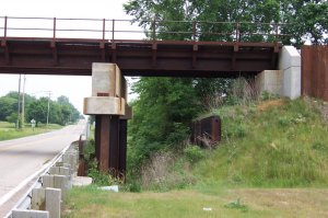
Of note is that other disused steel foundation in the 1st picture, makes me wonder if the bridge height has been raised to provide more road clearance. Does seem strange that raw steel would be used in what appears to be a creek bed, so in this case the steel columns may be sitting on concrete pads above what would be considered normal water levels at least, but why, if the bridge was raised at some time, concrete was used instead of steel to achieve that, is quite peculiar.
I think that is steel reenforcement for the bank. It looks like the steel around the top of the abutment. It looks like the steel used by the Army corp of engineers to reenforce the levees after Katrina. I am thinking its really unstable fill underneath the embankment.
Sent from my XT1080 using Tapatalk
Sent from my XT1080 using Tapatalk
I think that is steel reenforcement for the bank. It looks like the steel around the top of the abutment. It looks like the steel used by the Army corp of engineers to reenforce the levees after Katrina. I am thinking its really unstable fill underneath the embankment.
Sent from my XT1080 using Tapatalk
Local knowledge to the fore, certainly sounds feasible, still seems an odd ball method for the support. Steel on top of concrete, yes, the other way round seems strange.
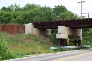
In the second picture, you can see that the steel pilings are on either side of the bridge/track. This suggests that they were done after the bridge was in place. I would guess that the original pier either settled/sank, or decayed for whatever reason. Then the new steel pilings were driven on either side of the bridge, and then tied together with the steel and concrete crossmembers.
marriedshades
Member
they used concret when they replaced the decks in newton it was for weight and the brige is over 100 years old. There was some settling and there was shifting.
Most bridges across creeks here are built of concrete and to a similar style. The big difference is that the columns are also concrete, those steel ones just don't look logical. It begs the question of how it was constructed, especially if it was a repair/restoration. Were the concrete pads the beam is sitting on placed on top of a flat steel plate on top of the columns? Were they cast in situ around the tops of the columns requiring boxing to form them? Then, presuming the beam is prestressed reinforced, how was it lifted and slid between those pads and the steel bridge, (assuming it wasn't also lifted off it's buttresses). If this is how it was originally built, then that brings back the question, why concrete on top of steel? Strange and weird also.
It looks to me like the steel pilings are on either side of the bridge structure, which tells me that they were done afterward, so the original pier must have needed replacing. Maybe it settled, or the concrete deteriorated.
You'd almost think I said that before, LOL.
Sent from my Vic20 using Java Moose
You'd almost think I said that before, LOL.
Sent from my Vic20 using Java Moose
I think that's the funniest answer yet.Just like when we build a kit and have some parts left over, they had some bits from some other bridge.
Sent from my XT1080 using Tapatalk
I just noticed this very interesting photo puzzle, and read the posts. Although the thread seems to be 'dead', it seems to be an unfinished topic.
While I am neither a civil engineer nor a local, I suspect the original underpass had a sunken roadway, which from past experience can fill with heavy rains and poor drainage. Perhaps the railroad was impelled to raise the track-bed (as the steel buttresses along the right-of-way suggest.) Then the underpass was back-filled to eliminate the road dip (which would explain the otherwise curious depressions to either side of the road.) As 'Toot' suggests, it would then be logical to put a very heavy load-damping cap on the pilings which support the center span of the bridge. That would minimize the tendency of passing trains to act as pile-drivers, which could result in settling/destruction of the span. It appears the engineers may have calculated this method of support (to reduce the bridge span) to be cheaper than using a much bulkier and longer span, which would have required very robust and expensive bridge abutments, as well as possibly requiring an even higher displacement of the rail bed.
In case anyone has better insight, I would be interested.
Jim W
There is a railroad bridge over one of our local streets that is currently steel/concrete. Near either end of the bridge, you can see the remains of wooden supports that have been cut off and removed, so the new bridge could be built over the location. There is graffiti on the current bridge dating to the early 1970s, so it was done before then.
I just noticed this very interesting photo puzzle, and read the posts. Although the thread seems to be 'dead', it seems to be an unfinished topic.
While I am neither a civil engineer nor a local, I suspect the original underpass had a sunken roadway, which from past experience can fill with heavy rains and poor drainage. Perhaps the railroad was impelled to raise the track-bed (as the steel buttresses along the right-of-way suggest.) Then the underpass was back-filled to eliminate the road dip (which would explain the otherwise curious depressions to either side of the road.) As 'Toot' suggests, it would then be logical to put a very heavy load-damping cap on the pilings which support the center span of the bridge. That would minimize the tendency of passing trains to act as pile-drivers, which could result in settling/destruction of the span. It appears the engineers may have calculated this method of support (to reduce the bridge span) to be cheaper than using a much bulkier and longer span, which would have required very robust and expensive bridge abutments, as well as possibly requiring an even higher displacement of the rail bed.
In case anyone has better insight, I would be interested.
Jim W
I'm fairly confident these are just precast pile caps that are set onto the steel piles. The steel piles have either been driven down to bedrock or set into concrete footings. The process is fairly simple and quick in that one doesn't have to cast or cure concrete.
I'm fairly confident these are just precast pile caps that are set onto the steel piles. The steel piles have either been driven down to bedrock or set into concrete footings. The process is fairly simple and quick in that one doesn't have to cast or cure concrete.
I agree. The use of precast reinforced concrete pile caps would make economic sense, as the newly elevated bridge deck could be placed and used immediately, thus reducing lost revenue and costly traffic diversion. In a similar vein, I surmise the use of steel retaining walls along the right-of-way would have expedited raising the track and considerably reduced the volume of fill otherwise required to elevate the bridge approached to the newly raised deck. Placing the pilings outside the span width would have permitted use of the right-of-way during the pile-driving process.
It would have been interesting to see how the construction process was managed to accomplish such a large task while minimizing time and expense. In writing this and considering your note, another thought occurs to me which might explain the use of such apparently oversized piling caps: perhaps it has nothing to do with vibration damping.
Is it possible that the construction used rock delivered by rail, and that this required the roadbed to be gradually raised on both approaches simultaneously? If so, the span could have been temporarily placed at the top of the pilings and jacked up gradually as material was added to the approaches, until the desired height was achieved, at which point the permanent piling caps would be inserted?
In any case, hats off to the original poster (Greg @ mnrr) who spotted the curious construction. I wonder how few of the thousands of passers-by have even given a second's thought to the scene. I am considering modeling such a site, once I have built a space for a layout.
I expect there are certified civil engineers capable of exposing my ignorance. I would be delighted to learn from them!
Jim W


