Help with SVdA Error Code with Prodigy DCC


Thank you! I just downloaded an article that shows that and even mentioned that taking a Peco turnout right out of the box and installing it will guarantee a short. I'll insulate the 3 turnouts I have so far and others down the line. Will post the results.

It will be interesting to see if this ended up being the problem. Sounds like it could be. I eventually got around my shorting issues by running all power through a Tam Valley booster. It acts as a circuit breaker as well and handles the tiny shorts before they even get to the command station. Makes my layout much more controllable.
 
It will be interesting to see if this ended up being the problem. Sounds like it could be. I eventually got around my shorting issues by running all power through a Tam Valley booster. It acts as a circuit breaker as well and handles the tiny shorts before they even get to the command station. Makes my layout much more controllable.

One of the posters mentioned that if you have Peco Electrofrogs and they are in a loop layout, insulating them or cutting gaps in the point rails just beyond the frogs is a must. My layout is a 5'x16' basically rectangular loop layout with a loop within that. One of the turnouts will be for setting up a yard. Everything is glued down, so I won't use the insulated rail joiners on those. I'll cut a small gap on the point rails for them. Other turnouts that will be added will have the insulated rail joiners. I won't be powering the turnouts with machines - they will all be hand thrown.

Here's a great reference on Peco Electrofrog and Insulfrog turnouts: https://dccwiki.com/PECO_Electrofrog#/media/File:ElectroFrog-Shorts.png
 
Well, I got the Dremel out with a metal cutting disk and cut gaps on the point rails (after the frog). Plugged in the power and NO error code! Checked track voltage and it's good. Put one of my DCC engines on the track right near the power connection and NOTHING. I tried putting the engine on the outside loop with all turnouts lined for the Main, still NOTHING. I had the correct engine ID but didn't matter. I checked all the rails again and there's nothing making contact with them. I hope that my new engines didn't suffer when the error code first appeared, although it's my understanding that the MRC power supply reacts fast when it detects a short, so hopefully it didn't affect the engines.

So, what now?
 
(Are you from Brooklyn, NY? I grew up on Staten Island)
I am from Brooklyn originally, Bath Beach / Bensonhurst area just over the bridge. When I was a teenager, the Bay Ridge Model RR Club let me join as a junior. They had a giant O-Scale layout in the basement of an apartment building which looked out under the bridge at Staten Island. Sadly, they shut the doors a couple of years ago when the landlord was forced to do work on the building.
Anyway, I now live in Columbus, Ohio. Came here for college and met my wife, yadda yadda yadda, I think you know the rest. Now I have a small HO layout with my 6yr old son. Brings me a lot of joy that he likes the modeling part.
 
Well, I got the Dremel out with a metal cutting disk and cut gaps on the point rails (after the frog). Plugged in the power and NO error code! Checked track voltage and it's good. Put one of my DCC engines on the track right near the power connection and NOTHING. I tried putting the engine on the outside loop with all turnouts lined for the Main, still NOTHING. I had the correct engine ID but didn't matter. I checked all the rails again and there's nothing making contact with them. I hope that my new engines didn't suffer when the error code first appeared, although it's my understanding that the MRC power supply reacts fast when it detects a short, so hopefully it didn't affect the engines.
So the short circuit is gone. There is power to the track (you checked at the track and not the output of the power supply, correct?). BUT your new locomotive doesn't run. I would not think that the short would hurt the locomotive, usually the decoder in the locomotive is only damage if IT is the cause of the short which is not the case here.

Tell me more about what you mean by the correct engine ID? Almost all DCC locomotives come from the factory on channel #3. I think the first thing I would suggest is to read and follow the procedure for the locomotive's "reset" to factory defaults.

Believe it or not, resetting to factory defaults was what I am going to do next. And I did check the track at different locations with a multi-meter and they all had power. Thanks for following up on this. I'm learning!
 
Believe it or not, resetting to factory defaults was what I am going to do next. And I did check the track at different locations with a multi-meter and they all had power. Thanks for following up on this. I'm learning!

Now I'm dealing with track power issues. I had an engine running and it would stop. I checked that area and put the multi-meter on the rails. Good power and then no power after the joint. I took a needle nose pliers and pinched the rail joiner on both ends. Meter again and the power is there. I let the engine continue and after going nice and smooth entering a turnout from the diverging side, it stopped. There was track power on the turnout (stock rail and point rail) but none after the gaps I had cut to resolve the short issue.

Reminder: I am using manual throw, no turnout machines. The info on these turnouts said to use insulated rail joiners (I can't as the turnouts are glued down) OR cut small gaps after the frog. Mine now look like the photos on the DCC Wiki info.

No short, but now no power routing after leaving the turnout.

????
 
So the short circuit is gone. There is power to the track (you checked at the track and not the output of the power supply, correct?). BUT your new locomotive doesn't run. I would not think that the short would hurt the locomotive, usually the decoder in the locomotive is only damage if IT is the cause of the short which is not the case here.

Tell me more about what you mean by the correct engine ID? Almost all DCC locomotives come from the factory on channel #3. I think the first thing I would suggest is to read and follow the procedure for the locomotive's "reset" to factory defaults.
 
When I put the engines (one at a time) on the test track they powered up. Each engine's ID is # 3 so I will be changing the second one to #2 when I have the #$#$%$%%ing layout finished. 😄 Not an issue right now. And I didn't have to do any resets.
 
How many power drops do you have? meaning in how many spots do you have power connecting to the rails. The Peco turnouts typically run power through them so the cut(s) you made to resolve the short may have created "dead" spots that you hadn't intended. Might need to run power jumpers after the diverging to the two lines just to make sure the whole thing has power (or at least has power where you want it to have power).
 
How many power drops do you have? meaning in how many spots do you have power connecting to the rails. The Peco turnouts typically run power through them so the cut(s) you made to resolve the short may have created "dead" spots that you hadn't intended. Might need to run power jumpers after the diverging to the two lines just to make sure the whole thing has power (or at least has power where you want it to have power).

That makes sense. I thought about it yesterday. I had held off installing the Main Bus and the Accessory Bus as I was still building the layout, but will now proceed with it as 90% of the track is laid.

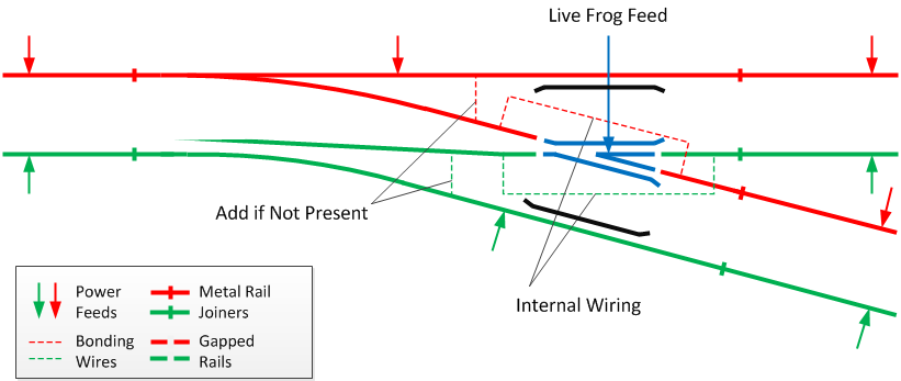
Here's a shot of the Electrofrog with wiring from power drops shown. When I first saw this, I thought it had to do with powering the switch machines which I'm not doing. Does this look like what you are referring to? (where insulated rail joiners are shown, that's where I cut the gaps)

I better double the Advil for the bus wirings. LOL I'll update this when done. Maybe it will help some other poor sods starting up a layout in our 70s) Thanks for the advice!
Screenshot_2021-02-06 EFInsulated1 jpg (JPEG Image, 1000 × 351 pixels).png
 
Here's a shot of the Electrofrog with wiring from power drops shown. Does this look like what you are referring to? (where insulated rail joiners are shown, that's where I cut the gaps)

I better double the Advil for the bus wirings. LOL I'll update this when done. Maybe it will help some other poor sods starting up a layout in our 70s) Thanks for the advice!View attachment 124350
I always say, don't invent problems that don't really exist. There was a fellow that was here a few years ago who spent I don't know how much time and energy, working above his skill level, reworking turnouts only to find he was solving a problem that didn't exist in his particular situation.

The diagram looks fine (other than the spelling of BUSS which is a form of kiss. An electrical busbar is abbreviated just bus), but the feeds after the frog don't need to be RIGHT THERE. That was just done to make the diagram compact. The feed could 3' or 6' down that track, as long as it is somewhere that direction. Don't remember how big your layout is, but I always like to use the measure of what is the furthest a locomotive can get to a power feed. Feeds in the middle of 6' power feed blocks means the loco is never more than 3' from "fresh" power.

I find it interesting that all this was common knowledge to all of us old sods who started modeling in the early 1960s. Back then, everything even Atlas was the equivalent of an "electrofrog" turnout.
 
This might be a slightly better schematic. One of the points rails in your shows the wrong polarity. Plus this shows the frog as an isolated unit:
TurnoutWiring.png


Back
Top