victortorgrimson
New Member
Hi,
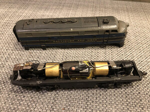
My 8 year old twins and I are starting to work on my Dad's old model railroad. I was considering trying to convert some of his old DC locomotives to DCC. I would guess this locomotive is about 50 to 65 years old. It runs well. I recall my Dad put new motors in many of his locomotive about 20 to 30 years ago.
I opened it up and I'm trying to understand the wiring of it and the implications for converting it to DCC. I'm hoping you might be able to help me with a few newbie questions:
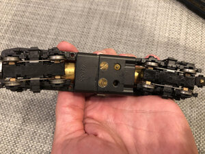
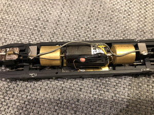
1) The two gray wires from the pick-ups and the two yellow wires to the motor appear to all four be soldered to each other. Is that unusual, and could I just disconnect them and add the decoder at that point?
2) In the middle foreground of the picture there is another wire that I guess is going from the motor to the bottom of the frame. What is that for? Is the black and pink on it a resistor?
3) The headlight has one wire going to the wire I mentioned in #2 and another going to the frame. So I guess the headlight must be running its circuit through the frame? Should I remove the wire in #2, remove both of the headlight wires, and just wire an LED into the decoder?
4) Does it seem likely that the motor is still not going to be isolated from the frame, which I gather would be a problem for DCC?
Thank you for any help with my newbie questions! I've searched a lot of websites and videos but haven't spotted this scenario.
Victor
My 8 year old twins and I are starting to work on my Dad's old model railroad. I was considering trying to convert some of his old DC locomotives to DCC. I would guess this locomotive is about 50 to 65 years old. It runs well. I recall my Dad put new motors in many of his locomotive about 20 to 30 years ago.
I opened it up and I'm trying to understand the wiring of it and the implications for converting it to DCC. I'm hoping you might be able to help me with a few newbie questions:
1) The two gray wires from the pick-ups and the two yellow wires to the motor appear to all four be soldered to each other. Is that unusual, and could I just disconnect them and add the decoder at that point?
2) In the middle foreground of the picture there is another wire that I guess is going from the motor to the bottom of the frame. What is that for? Is the black and pink on it a resistor?
3) The headlight has one wire going to the wire I mentioned in #2 and another going to the frame. So I guess the headlight must be running its circuit through the frame? Should I remove the wire in #2, remove both of the headlight wires, and just wire an LED into the decoder?
4) Does it seem likely that the motor is still not going to be isolated from the frame, which I gather would be a problem for DCC?
Thank you for any help with my newbie questions! I've searched a lot of websites and videos but haven't spotted this scenario.
Victor