Milwaukee Road 113
Milwaukee Road addict...
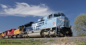
True, didn't see it for those trees...


.jpg")
.jpg")

Logandsawman:
Since these are end cab switchers, it doesn't matter how you face them. As low speed locos, they were typically used in yards and on locals. Lots of back of forth, and with the cab on one end, it gave the engineer visibility at three of the four corners to watch the brakeman.