DCC Decoder Warm


Hi,
I am for the first time upgrading a DC locomotive to DCC. Its an Athearn locomotive and I am using a Digitrax decoder. I am greatly benefiting from videos by Dennis461 and the DCC Guy.

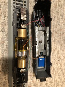
I initially had some success, but it quickly failed. I had some sparking inside the engine and I'm pretty certain I fried the decoder. I had followed the recommended approaches to isolate the motor from the frame, however it became apparent to me that I was still getting current transfer from the frame to the motor. So I've done more extensive taping between the frame and motor. Now when the engine is stopped on the tracks, a voltmeter reads about 39 mV when I test the current pickups. And if I touch it to the one current pickup and the motor, I'm only getting 1 mV or less. Is that sufficiently low that I can consider the isolation successful?

I have a new decoder on order, but before I put it in, I'm testing things out with the malfunctioning decoder to reduce the risk that I might fry the new decoder. The old decoder still lights the LED headlight, and occasionally will move the engine a bit, but usually the engine won't move. (The motor had been working fine, and I swapped another working motor in with no change, so I'm fairly certain the motor is fine.) I notice that when I turn the power up, the deocder is getting quite warm to the touch. Is that normal or does that mean I've still got a problem?

I have the decoder touching the bare metal top of the locomotive shell, should that matter?

Thanks for any tips for a newbie,

Victor
 

Attachments

  • image_67230209.JPG
    image_67230209.JPG
    473.5 KB · Views: 162
Let's start with the motor. The two power leads on a Sagami should have NO connection with the metal motor case; check with an ohm-meter.
Next, the motor metal case should be isolated from BOTH the frame and the top mounted weight.
You may need to wrap it; I use plastic bag from cereal boxes.
The decoder looks to be covered/insulated. Make sure no part of the board poked through the blue cover.

Now for warm.
Can you get it to the program track with engine shell off and try a factory reset? Warm is not good.
 
When you insulate the motor from the frame, not knowing the model of the locomotive, be sure that any fasteners that are used to attach the motor to the frame are non-conductive.

Greg
 
My guess is something is shorting on the weight. In the photo, it looks like there is a resistor peaking out but I can't see any shrink wrap or tape on it. Does the decoder wrap have any burn marks on it?

Did you do the continuity tests, the 1mV or less, with the decoder installed? Without the decoder it should be an open circuit.
 
Thank you for the help! I have been mostly successful.

Resetting the decoder to factory default did stop it from getting warm, although it was still non-functional. When I put a new decoder in, it worked.
I added insulating tape to the weight. And I verified the leads have no connection with the motor mount. So my short circuits have stopped.
Since I only have conductive screws, at the moment I have the motor taped into place.

The last problem I have is the engine works if I partially screw the shell on, but if I tighten the screws then the flywheels are rubbing on the weight. They must have had incredibly little clearance because I've barely changed the clearance. But with the motor not screwed in, it does sit a tad higher than when I screw it in. So I'm thinking the final step is I need to get some non-conductive screws to screw the motor down securely.

Is the best way to get non-conductive screws just to try to match them on a site like mcmaster.com?

Thanks again for the help!

Victor
 
I don't see where the motor is screwed down but on the Sagami motor, the only places you need to worry about isolating are the two tabs where the wires are attached. The electricity goes from there to the brushes and the motor case is totally isolated. I have locomotives that use the frame as part of the circuit and the can motor is screwed to a brass bracket and that is screwed to the frame.
 
Thank you for that clarification! Indeed, I was able to screw the motor into the frame and it worked. From the voltmeter I can see that is causing power to go the motor casing, but its not causing any issue. I had misunderstood and thought that power getting to the motor casing would be a problem. So I think this means I was doing a lot of unnecessary work putting insulating tape under the motor and on the weight.

I am wondering if you could clarify for me: On a Sagamai motor, does isolating the tabs, just mean make sure you don't have the wire going to them or the solder touching the motor case? Or is that end of the motor where the tabs are even conductive? (I see the end is a different color than the rest of the motor casing, so I wasn't sure if the end of the motor was a non-conductive material.)

Thanks,

Victor
 
The tabs should only be connected to the gray and orange decoder wires, nothing else. Yes, make sure there is no connection between the tabs and motor case. The end of the motor is usually an assembly containing the brushes and brush holders. See this link for a photo:

Bare wire connections can short against the weight, frame, motor case, etc. so they should always be wrapped with shrink wrap or otherwise secured so they don't let the electrons get out of line. Also make sure the connections on the decoder won't touch anything metal. Some hardwire decoders don't have shrink wrap.
 
Thank you for everyone's help with this! After lots of mistakes and lots of learning I got it all working. I did two locomotives, adding sound to the second one. Indeed it turned out isolating the motor case was irrelevant with these motors. I suspect that in an earlier version I probably did have the gray wire touching the base, which would explain some of the early problems I had.
After everything I learned from doing the first one, the second one was easy. Soon I'll start working on one of the steam engines.
Here is a little video of the result:
 
Good job. Now program the second unit to run normally in reverse, and turn it around. Steam is easy with tenders.
 
There is a CV (I forget which) that you set to reverse the trailing unit so it runs backwards with your DCC controller set to "Forward". That way the trailing unit will run back-to-back with the lead unit. True, some railroads (notably the Burlington Route) would sometimes run "elephant style", but not always. The advantage to running back-to-back is that you don't have to turn the engine lashup around to go the other way.
 
It is usually CV29 but unless they will never be separated, I'd consist them. You didn't mention which DCC system you use but consisting involves less figuring than computing a value for CV29.


Back
Top