Hi - I'm building a small n scale switching layout that is in an L shape - 10 feet x 2 feet on the long side with a 6 feet x 2 feet extensor on one end. I'm going to use solid core 14 gauge wire for the DCC bus, preferring to solder the track feeders versus the suitcase connectors which I imagine would require stranded bus wire. I have read that the two bus wires should be twisted. This would make it a little more difficult to strip sections for the track feeder connections. The question is - for this small layout is it really necessary to twist the bus wires? Thank you for any thoughts.

You are using an out of date browser. It may not display this or other websites correctly.
You should upgrade or use an alternative browser.
You should upgrade or use an alternative browser.
DCC Bus Wiring
- Thread starter rreitz
- Start date
Selector
Well-Known Member
There is no practical purpose for winding, as in helical, the two wires of a DCC bus under distances of about 30'. Some argue that it is only important at even larger distances. Same for using a snubber at the end, instead of just capping them off apart from each other. No need.
In fact, unless you already have it on hand, you could easily get away with 16 gauge for a bus. Well, in truth, there's not much call for a bus at all, not even for a 10' long oval. I'm not saying I'm against it, I'm just saying that you could run two wyed pairs of feeders to opposite sides of the oval and have plenty of robust power with minimal voltage loss. But if you insist on the bus, 16 gauge would be fine, and run 22 gauge feeders up to the rails.
In fact, unless you already have it on hand, you could easily get away with 16 gauge for a bus. Well, in truth, there's not much call for a bus at all, not even for a 10' long oval. I'm not saying I'm against it, I'm just saying that you could run two wyed pairs of feeders to opposite sides of the oval and have plenty of robust power with minimal voltage loss. But if you insist on the bus, 16 gauge would be fine, and run 22 gauge feeders up to the rails.
Smudge617
Well-Known Member
I agree with selector, winding will just make more work for yourself with no benefit to the layout. But I would run feeders at quarter distance. (but thats me). Some fit feeders on every section of track, but personally I think thats a bit of an overkill, I have mine every 2-3 feet, and at the end of each track in my switching yard,(more of a just in case), no issues so far, just ensure that your track is firmly fixed down to the board, or you will have issues.
Last edited:
There is a non-obvious reason for twisting the wires, it reduces RF interference emanating from the layout. You don't need a twist every inch to make it work, even if they're loosely wound like a twist every one or two feet is enough. Mine are not twisted right now, but I'm going to fix that because I can hear horrible splatter all over the bands on my radios when the DCC system is on. If not twisted, they at least need to be closely spaced to avoid interference. Any "loop" wiring is a transmit antenna.
wvg_ca
semi flaccid member
usually there is no need to twist, with the possible exception of really close ham radios...and feeders every three feet is enough ... same with no need to put snubbers on the ends of the dcc bus for such a short distance ..
i ran bus lengths of thirty feet [center to end] with none of the twists or subbers
i ran bus lengths of thirty feet [center to end] with none of the twists or subbers
2Tracks
Ol' School
Well, close, but it's the other way. Suitcase (or IDC's--insulation displacement connecters) work best with solid wire. My layout was an around the walls/peninsula style in a 12x20 room. HO I contemplated either soldering or using the idcs and settled on idcs. Certainly, soldering is more robust, but for me, looking ahead on the wiring I was going to have for my layout, and how many times I was going to be underneath "racking" on the wiring? Idcs it is. But, installing the idcs, I used the correct connecter for the wire size, the correct application tool, and installed them in the correct manner.preferring to solder the track feeders versus the suitcase connectors which I imagine would require stranded bus wire.
I looked at the twisted wire & snubber applications for my layout, I thought my far piece of track was right at the limits for distance for twist or no twist. I did not twist the wire or use a snubber and all my power operated ok. However, I'm going to build a new layout, and this time I'm going to twist the wires. If there's a possibility that this will help operations be more reliable, I'm for it....
That's interesting about IDCs working best with solid wire. I visualized a splade of some sort wedging itself between the individual strands of wire in stranded wire. So how do they work - when properly installed are they just pressed against a small section of the solid core wire and held there by the pressure of the case around the splice?Well, close, but it's the other way. Suitcase (or IDC's--insulation displacement connecters) work best with solid wire. My layout was an around the walls/peninsula style in a 12x20 room. HO I contemplated either soldering or using the idcs and settled on idcs. Certainly, soldering is more robust, but for me, looking ahead on the wiring I was going to have for my layout, and how many times I was going to be underneath "racking" on the wiring? Idcs it is. But, installing the idcs, I used the correct connecter for the wire size, the correct application tool, and installed them in the correct manner.
I looked at the twisted wire & snubber applications for my layout, I thought my far piece of track was right at the limits for distance for twist or no twist. I did not twist the wire or use a snubber and all my power operated ok. However, I'm going to build a new layout, and this time I'm going to twist the wires. If there's a possibility that this will help operations be more reliable, I'm for it....
I agree with selector, winding will just make more work for yourself with no benefit to the layout. But I would run feeders at quarter distance. (but thats me). Some fit feeders on every section of track, but personally I think thats a bit of an overkill, I have mine every 2-3 feet, and at the end of each track in my switching yard,(more of a just in case), no issues so far, just ensure that your track is firmly fixed down to the board, or you will have issues.
Nice! Thanks for the pic. The IDCs do look a lot easier than soldering. I have spools of 24 gauge wiring on hand I was going to use for the feeders. Hope that is not too small - a post above suggested 22.Here is a pic of the wiring underneath the yard, my most congested spot electrically.
View attachment 137878
I ran feeders to every piece of track.
2manyhobbeez
New Member
I don't know about the comment that IDC connectors work better with solid wire. I'd like to see the data that justifies that statement. These connectors are recommended by the manufacturer for auto and marine use. Those environments typically use stranded wire and the environment is hostile. Follow the directions for installation and you will be fine. Also avoid knockoffs.
I am using ScotchLok 952 connectors. These have a spade connection for the branch. This is good for circuit isolation when troubleshooting.
As an aside, there is a better way to wire a railroad. Thin copper or brass straps can be laid on the surface right under the track. Uninsulated feeders can then be soldered to the strips and the rail. Then only a single feeder from the bus needs to come up through the plywood/foam/whatever and soldered to the strip. This method removes all the spaghetti from underneath and eliminates most of the IDC connections. If your preference is to solder feeders to the bus then it eliminates bits of molten metal dropping on your face too.
George
Edgewood, WA
2Tracks
Ol' School
Alright, I tried an idc with stranded wire. That seems pretty darn robust. Admittedly, when I was first looking at using idc's for the wiring, I don't recall hearing/seeing about them being used on stranded wire, and I could not imagine how the idc spade could grip multiple wires that, to me, seemed prone to moving. And since I was going to solder the feeders to the rail anyway, which solid wire would seem easier to do, I never gave stranded another thought. I stand corrected! Good info!
So, is stranded wire fairly easy to solder to the web of code 83 rail? Never tried it......
So, is stranded wire fairly easy to solder to the web of code 83 rail? Never tried it......
Thanks for the tip! I was thinking stripping just a section out of the middle of the cable would be the hardest part.If you do decide to solder feeders to the buss wire, the hardest part is stripping the wire. I picked up a set of Klein wire strippers. A couple of seconds and a squeeze on the handles, done! You are stripped!
Interesting idea. Sort of like a 'sub-bus' on the table top then connected to the main bus below. I've hand laid code 40 rail using PC board ties so there is a convenient soldering tab at the end of each tie. Will look into that in various spots where the wiring could get congested.I don't know about the comment that IDC connectors work better with solid wire. I'd like to see the data that justifies that statement. These connectors are recommended by the manufacturer for auto and marine use. Those environments typically use stranded wire and the environment is hostile. Follow the directions for installation and you will be fine. Also avoid knockoffs.
I am using ScotchLok 952 connectors. These have a spade connection for the branch. This is good for circuit isolation when troubleshooting.
As an aside, there is a better way to wire a railroad. Thin copper or brass straps can be laid on the surface right under the track. Uninsulated feeders can then be soldered to the strips and the rail. Then only a single feeder from the bus needs to come up through the plywood/foam/whatever and soldered to the strip. This method removes all the spaghetti from underneath and eliminates most of the IDC connections. If your preference is to solder feeders to the bus then it eliminates bits of molten metal dropping on your face too.
George
Edgewood, WA
Smudge617
Well-Known Member
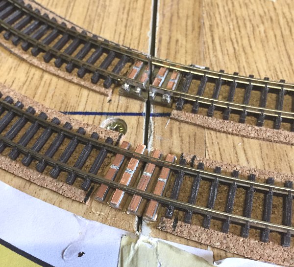
Have you thought about something like Copper Clad Board, or even something like this? It's a sleeper with copper ends, you replace a sleeper with this and solder a wire a dropper to it, then ballast over.

Or make your own
 modelrailwayengineer.com
Or make your own
Laying track across baseboard joints
If you're laying track across baseboard joints you'll need to secure the track rails at the edges. The tried and tested technique for this is Copper clad sleepers. Modeller David Cooper reveals how to make your own sleepers and his technique for fitting them.
modelrailwayengineer.com
Very timely post indeed! I actually have a 2 x 6 foot L section of this layout bolted on to the 2 x 8 foot section so that it can be separated for moving purposes. There will be 4 places where track runs over the two sections that will have to be cut when separating the two modules. This is a great idea for securing the tracks where the cross over that I have not thought about yet.
Smudge617
Well-Known Member
Yeah, there's a myriad of information out there, this guy is one of the best in the UK, another source of information which covers everything from Baseboards to buildings to electrical, etc. and he has his own model railway website which your free to roam and get ideas, tips etc. check it out.Very timely post indeed! I actually have a 2 x 6 foot L section of this layout bolted on to the 2 x 8 foot section so that it can be separated for moving purposes. There will be 4 places where track runs over the two sections that will have to be cut when separating the two modules. This is a great idea for securing the tracks where the cross over that I have not thought about yet.
Home
He's OO scale, but it will work in other scales too.
