Crossing Gate Lighting Help Wanted


UPDATE April 20, 2021

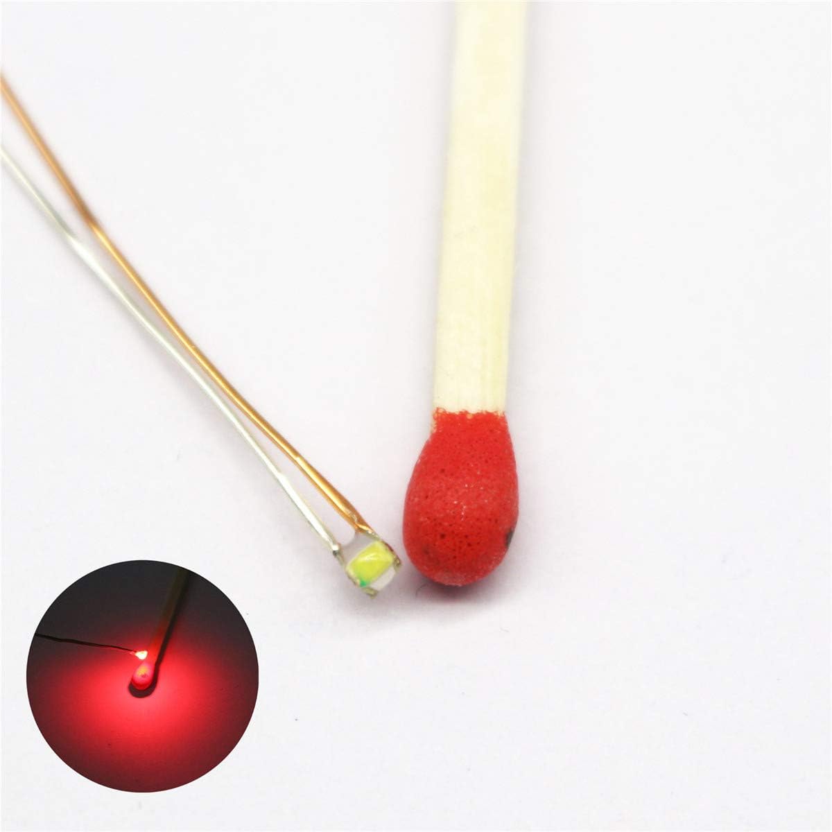
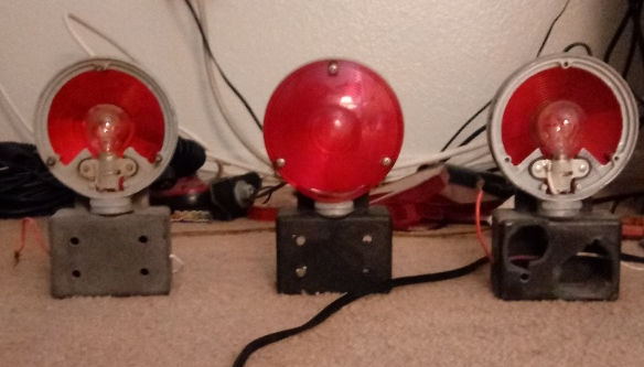
Finally after about six weeks, maybe more, of waiting, my Micro Modz LEDs showed up! I ordered them on the 4th of last month and they finally showed up today (although if I didn't have a doctor's appointment yesterday or maybe got home sooner, I would have gotten them yesterday!) Anyway here they are
ModelModz LEDs.png

Yes, that's them! In the Off position, they would appear invisible and they're that small, they're speck-sized LEDs, maybe smaller than a speck!

That's just it though, these LEDs were smaller than I expected them to be, I didn't think they'd be that discreet! But the good news is they do work! But I had to figure something out on my own and this is important, at least to people who never bought these before and might be planning to. I tried wiring the red wires to the light terminals and the black wires to the Common Ground/Out terminal on the flasher unit, but as it turned out I wired them backwards! The black wires go to the light terminals and the red wires go to the Common Ground terminal! I wired these to more than one flasher unit before realizing I had gotten it wrong!

Before we go on, although you see two, I ordered two individual LEDs (you only get one per order) and paid twice as much as I would have if I'd only gotten one (1), which technically I should have. It is a good thing I got two though because it was my chance to see them alternately flash as you will see in my next pictures.

I'm debating if I'm going to buy more of these from ModelModz, I've been considering buying LEDs from Wish.com as well, they too come with prewired Nano LEDs but it isn't said if they come with resistors, and I'm having trouble finding other manufacturers that do prewired Nano LEDs with resistors, so Model Modz is what I'm stuck with. Wish sells 0402 and 0603 SMD Nano LEDs, and I'm wondering if the LEDs I got from Model Modz are like the 0402 LEDs and if maybe I should have get the 0603. I won't know unless I order them and see! https://www.wish.com/search/Red Nan...a725b0116a?source=search&position=4&share=web

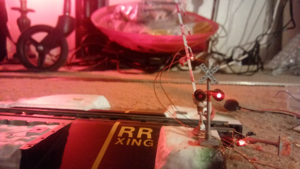
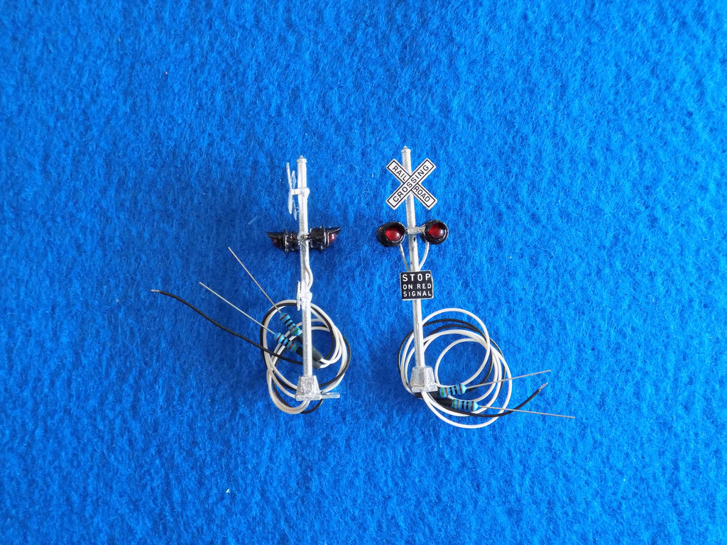
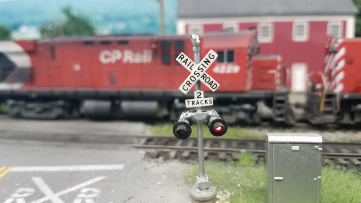
Now without further ado, see pictures of the Model Modz LEDs along with my Busch 5934 HO crossing signals!
Busch Signal, NJI Gate, and ModelModz LEDs 1.png

Busch Signal, NJI Gate, and ModelModz LEDs 2.png
Busch Signal, NJI Gate, and ModelModz LEDs 4.png


No I haven't removed the fake lights from the crossing gates, I won't right now although I'm not sure how to at this time! But I did want to see and show what the LEDs would look like mounted on the gate arm. I used clay to hold the lights in place. The stripes on the gate are fading, probably because while trying to put the lights on I was rubbing my fingers and thumbs against them and something on my fingers and thumbs must have made them fade. To be fair I had these gates since 2005 so they are kind of old!

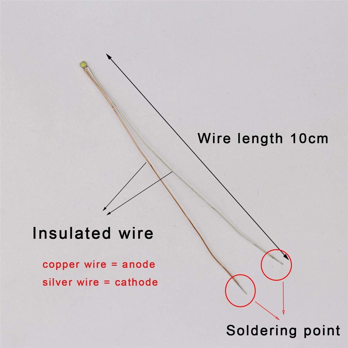
I also wired the Model Modz LEDs to the flasher unit the Busch crossing signals came with. I put the black wires on the side terminals and the red wires in the middle terminal. Seeing how the copper wires are all the same color and can easily get mixed up if you take them all out at once, I did it one terminal at a time! But yes the Model Modz LEDs work well with the Busch signals and will flash alternately although they will be dimmer. When I wired these to my Circuitron flasher unit and to a flasher unit formerly made by NJ International, the lights lit up brightly! A little too bright for comfort! But the Busch crossing signal flasher unit doesn't let these LEDs flash that brightly.

But seeing how crossing gates have three lights on them, one that always stays lit, I have a feeling that light is going to be the brightest lit light, brighter than the other two lights that will flash with the signals, and it wouldn't look right if one gate light was brighter than the other two when they should all be the equal amount of brightness! How I thought of doing this was wiring the flashing gate lights to the flasher unit but the solid tip-light to main power source (9V battery) but as I said that could make the tip light brighter than the flashing lights!

And so now I need a way to keep the lights from flashing too brightly and to make them as dim as or almost as dim as the flashing lights! But I also plan to flash the LEDs on the Circuitron flasher where I have signals from other manufacturers.

So my question now is do I order more LEDs from Model Modz, or should I try Wish, although I've been having trouble trying to get in contact with Wish, I cannot seem to get a live person to chat with me and get the automated chat. I also cannot seem to find their email address! So I don't know what to do with them! Maybe I'll just continue to buy from Model Modz for now and over time I can try Wish.

By the way my other Busch signal is lying next to the crossing but I only wanted to show one signal with a gate since only one gate is lit, sort of. Besides that signal lying on the ground is beheaded (the part above the lights that holds the crossbuck broke off when I was trying to fix a mispositioned LED on that signal!) Busch signals are very fragile and can break easily if you're not careful, and I try to be super careful with Busch signals!

That is all I have for you. But please check back for more updates! Thanks for reading. And thank you @McLeod for telling me about and referring me to Model Modz!
 

Attachments

  • Busch Signal, NJI Gate, and ModelModz LEDs 3.png
    Busch Signal, NJI Gate, and ModelModz LEDs 3.png
    698.6 KB · Views: 167
Hi all.

I've decided the ModelModz LEDs, while they work great, are just too small for me. I wanted discreet LEDs but they're a little too discreet and I think I want something a little larger, at least I think I do.

I am now considering using 0603 SMD LEDs instead and I think I found some I might want to use on Amazon. And I can get a 25 piece set for $10.00 (rounding off, not exact)
51%2BB9X5qb5L._AC_SL1200_.jpg

Amazon.com: 25pcs Pre-soldered Micro Litz Wired Leads Red SMD Led 0603 + Muti-Resistor New: Home Improvement I'd do Wish.com but I'm afraid to try them and I cannot seem to chat with anyone there but maybe I won't need to use Wish!

Yes they're going to be even brighter and a bit harder on the eyes than the ones I got from ModelModz but I'll see what I can do to fix that. Besides 25 pieces for $9.99? That's a great deal! I spent $11.50 on two individual LEDs from ModelModz (including shipping.)

I did a test purchase but didn't place the order and it's a little more than 10 dollars including tax So far shipping is free, at least until April 30th I think, but I don't plan to order until next month, hopefully the 5th or later. Admittedly I won't know what size these are so I don't completely know what I'm getting into until they come.

Thanks again for telling me about the ModelModz LEDs, but I would like my gate lights to be a little more obvious even when off.

Let me know what you think please.
@McLeod @GeeTee @Rico @flyboy2610 @trailrider (sorry if I'm bothering you guys, it's just that I haven't been getting a lot of replies from others, I don't know how big the Model Railroad Forum community is and it's very hard finding people that have the same goals and interests I have, I'm practically a minority! I would like it if more people found this post and answered it, respectfully that is!) I also hope you find Dwight, I could use some of his help please!

Also, I decided I'm not going to color the LEDs, I'm just going to leave them white for now. That or I'll cover them with Lithographic tape, that should lessen the brightness.
https://www.allelectronics.com/item/led-157/red-mini-axial-led/1.html

It really boils down to personal preference , you can get just about any LED you want in any shape ,color, mounting , lens ..ect . If you go through Digikey or Mouser.

With leads its a bit harder , you have to look at surplus places like All Electronics / Jameco

Both All and Harbor Freight have white LED strips , with 0603's ,that could be cut off and used .

https://www.allelectronics.com/item/sl-cw/mini-led-string-lights-cool-white/1.html

I found the same thing at HF last week.

If it were me, I would just get some 38 guage copper wire and order discrete LEDs with color and shape i wanted and solder them the way I wanted in parallel with enough lead length .
 
UPDATE May 6, 2021: Alright I just ordered some 0603 LEDs from Amazon Amazon.com: 25pcs Pre-soldered Micro Litz Wired Leads Red SMD Led 0603 + Muti-Resistor New: Home Improvement
51%2BB9X5qb5L._AC_SL1200_.jpg


I'm not sure how big or small these will be but hopefully they'll be bigger than the Model Modz LEDs. They should come on the 8th but let's expect them to come later.

I also ordered some 28 gauge wire Fermerry 28AWG Silicone Stranded Wire Hook up Wire Kit 28 Gauge Electronic Tinned Copper 6 Colors 10Ft Each Electric Wire (10 FT 6 Colors Each, 28AWG) - - Amazon.com It comes in six different colors (I actually only wanted two or three, the black, the red, and the white but I couldn't seem to find any individually sold wires, at least not on Amazon.

I also just bought nine more Jackson Electric Supply 7219R red bulbs to complete my collection.

More updates to come later, I especially plan to talk about the 0603 LEDs when they come. See you in two days or not too much more hopefully!
 
May 8, 2021

I was supposed to get my LEDs and wires today but unfortunately there was a delay in the package delivery

"Shipped with USPS

Tracking ID: REDACTED
Saturday, May 8
5:00 PM
Delivery Delay

7:19 AM
Package transferred to another carrier for delivery.
Tucson, AZ US
3:36 AM
Package has left the carrier facility.
Phoenix, AZ US
3:20 AM
Package departed an Amazon facility
Phoenix, Arizona US
Friday, May 7"

I knew today was too soon, and tomorrow's Sunday so no mail will be delivered! So now I have to wait till Monday! ☹

It's less than 48 hours and that's better than a week or especially a month!
 
UPDATE May 6, 2021: Alright I just ordered some 0603 LEDs from Amazon Amazon.com: 25pcs Pre-soldered Micro Litz Wired Leads Red SMD Led 0603 + Muti-Resistor New: Home Improvement
51%2BB9X5qb5L._AC_SL1200_.jpg


I'm not sure how big or small these will be but hopefully they'll be bigger than the Model Modz LEDs. They should come on the 8th but let's expect them to come later.

Those LEDSs look very interesting. Are you planning to wire them to a power supply or run from batteries. I wonder how long little 2032 batteries would last on a layout. I'm thinking of structure lights.
 
Those LEDSs look very interesting. Are you planning to wire them to a power supply or run from batteries. I wonder how long little 2032 batteries would last on a layout. I'm thinking of structure lights.

My aim is to use 9V batteries, it saves on electricity!

Mike Hickok, the original runner of www.rxrsignals.net, now sadly dead, told me personally I could use 9V batteries, which I use for LED lit signals. He also told me I can use a 12V AA battery holder for incandescent lights.

And seeing how I have a lot of signals now, won't even begin to count them right now!, and not so many wallplugs, batteries are a great alternative and though they run out eventually, they save on electric bills!😁

I just hope these LEDs aren't too small or too big, I plan to make these gate-mounted lights and plan to wire the "tip light" that stays on directly to the battery and the two inner lights to a flasher unit so they can flash with the crossbuck lights!
 
UPDATE May 10, 2021

I have received my 0603 LEDs today. I'll let you see them.
0603 SMD LED 01 (Single).png
0603 SMD LED 02 (Single, Closer).png


First I apologize for the blur in the photos. Like I did with my 7219R and 2162R incandescent bulbs, I put a dime next to the LED to compare sizes, although thinking back maybe now I should have put one of my 7219 bulbs in! I can come up with ideas too late! By the way that black surface is the base of my house shoe! I wanted something to make my LED(s) more obvious.

Like with my incandescent bulbs, these look to come with bare wires, actually the anode and cathode. So you'll know which is which, they say the anode is red (actually copper) and the cathode is silver, lighter colored than the anode. The lengths of the wires are 100mm. They're said to be insulated wires although I'm not completely for sure at this moment.
0603 SMD LED 03.png


These are six of my LEDs including the one in the top two photos, enough to light up two crossing gates!

0603 SMD LED 04 (All LEDs).png


All 25 of my LEDs including the six in the previous photo while the other 19 are still in the "bouquet" on the far left!

But that's not all, my LEDs didn't come alone!
0603 SMD LED 05 plus Dropping Resistors.png


With my LEDs came dropping resistors (we'll just call them "resistors" for short.) I got three different sets, and in case you cannot read them well, the ones on top are 9.1-14. 4V dc Use; the ones in the middle are 5.1-9V dc Use; the bottom row are 3.5-5Vdc use. Only now, which of these do I use because I plan to use a 9V battery to light these up although I may go 12V. I also plan to wire most of these to flasher units (for the "tip" lights they have to be wired directly to a power source.) They're 3V LEDs but I need them for 9V so I need to figure out which resistors to use.

Now this is where I'm having at least one problem: I did try lighting some of these but no matter how I wire them they won't seem to light up! I wired them one way and they didn't light up, then I wired them another way and they still didn't light up. I even tried connecting a resistor to three of the LEDs, trying one wire, then trying the other (anode or cathode I forget which I did first.) I also had to reverse the wires when wiring them to my 9V batteries and the LED still won't light up. I thought these would light up as easily as the Model Modz LEDs did (I also thought they'd come with the rubbery-like insulation like the Model Modz LEDs did and like what's on other wires including on the 9V battery snap wires!)

I also tried cork-screwing the wires and resistors but still no light-up! I didn't think I needed to solder them to make them light up, I thought just a simple temporary cork-screw wiring would light up the LEDs, although I do plan to solder them eventually, and I did get my soldering kit (tell you more about that in this post later (1) What Heat Shrinking Tube Should I Use? And about soldering. | ModelRailroadForums.com) I guess I do have to solder them in order to make them work. Or maybe I don't need to solder, just need to scratch off some insulation, only not sure how other than using the edge of a knife or scissors, which is what I use to peal off insulation.

Something else I tried to "marry" two LEDs, connecting their anodes together and wiring the cathodes to the power source, with resistor of course, (or did I connect the cathodes together and the anodes to the resistors and power source?) I thought that in doing so, marrying the LEDs, they can flash together and that it would be more efficient than trying to light all LEDs individually. (I now remember that I should have added a common ground wire to the married leads like I did with my incandescent lights!) Well maybe there's no need to marry the LEDs, (the "tip gate lights" don't need to be married since they won't blink anyway.)

One reason why I tried to marry the wires is because LED crossing signals come with three wires each, two that you wire to the L and R wires or terminals on the flasher unit, and the third one you wire to the common ground terminal or OUT terminal. So I figure you do the same with the blinking gate lights, wire one of their leads together, be it the anode or cathode, and then keep the other leads away from each other, wiring those to the power source (with resistors!) And add a common ground wire to the interconnected leads. Like I said, this is for the two inner lights that flash with the crossbuck signals.

I cannot solder yet because I still need the rosin-based flux, which won't come until June. Also I have to read the directions on how to use the soldering kit!

Now before I go, I have one more picture I'd like to show
0603 SMD LED 06 plus NJI 1172 gate 01.png


Three of my 0603 LEDs with one of my NJ International 1172 crossing gates! I already removed the fake lights off this gate although I cannot completely remove the pieces as you can see, they're too stubborn and I hate to damage the gate arm, the part I definitely still need!

But these LEDs are exactly the right size! Well they're not perfect but this is better than the Model Modz LEDs that were even smaller and is what I want to use for my crossing gates! And I don't need them to be any bigger! I didn't glue the LEDs on to the gate arms, I don't want to yet, not until I can get the LEDs to light up.

So once more, these are what the LEDs are and where the LEDs came from https://www.amazon.com/gp/product/B07P6L7P6V?ref=ppx_pt2_dt_b_prod_image. I learned they were manufactured by Bowerful.

I am wondering if I need to put heat-shrink tubes or liquid electric tape around them.

Thanks for looking. I await and would like further instruction and advice on what to do next and how to make the LEDs light up, and what I need to do to make them work from 9V batteries. And hopefully I can come back with another update.

Thank you.
 
Will - Firstly, if the anode and cathode on the led's are insulated, you must strip off some insulation to make contact with the power source.

Here is a simple schematic of the hook-up:
LED.png

I'd go for the 9-14v resistors. - the colored bands on the barrel of the resistor refer to the resistors value. You can research that through google. The resistor limits the current flow, and is hooked up in series with the LED.
 
I guess they are insulated, they just didn't look insulted, although they do show a picture of the wires at the soldering point on the item page
61vbPmzde4L._AC_SL1200_.jpg


Sorry, I'm not used to these types of insulated wires, this is new to me and I thought the wires were going to have a more rubbery or plastic-like insulation like the Model Modz LEDs did.

I looked at the image schematic and did try taking my LED and wires but it was confusing to me, still is. I say confusing because where it shows the plus (+) and minus (-) in the circle on the left, that's where I thought the LED was or should have been because the anode and cathode start from there and the resistor looked connected directly to the anode.

Where it shows where the LED is in the diagram, D1 and left arrow, that's what's confusing me because it makes it look like the resistor is connected between the LED itself and the anode instead of the anode connected directly to the LED, and where the +- are, where I thought the LED should have been, it looks like the anode is connected to the cathode. I also don't understand the two arrows pointing down and left.

Before we go any further, people, I am sorry if I seem difficult and immature and like I'm annoying. This happens everywhere I go, I feel like I'm annoying, upsetting, and even frustrating others and I don't mean to and hate annoying others, and this is why I don't like making others have to deal with me and one reason why I don't have a social life and prefer to keep to myself almost all the time. I'd rather be alone than get on other people's nerves! But I'm sorry if I upset and annoy any of you. I'm not an easy person to deal with or work with.😔 Now you've seen the real me!😳 At least some of it and now I feel ashamed!

Getting back to this topic, I did try using an unused LED, then tried connecting it to a 9-14 resistor, connecting the resistor first to the anode while connecting the resistor and the cathode to the battery. When that didn't work, I turned the resistor around, switching ends. That didn't work either, so I might have moved the resistor from the anode to the cathode, I forget if I did or not. I also tried switching the anode and cathode between the black and red wires to the battery snap connector, but no matter what I do, I cannot seem to get an illumination.

And I did try shedding off some insulation at the butt of the anode and cathode, although especially on the copper wire, it looked like there was no insulation, it's harder to tell on the silver wire, then connect, but that didn't work either. So I don't know if my LEDs work or not and they better not have sold me defective LEDs! Then again, I hope I didn't mess them up! Thankfully most of my LEDs are unused.

I also tried twist-tying the wires, again I cannot solder right now, I don't have the flux yet.

I'm just gonna have to email Bowerful since they're the manufacturer and know more about these LEDs than anyone else. I would have hours ago but I was too tired. But I'm going to email them and see what to do!

And I agree, I'm using the 9-14v resistors!

Thanks for the help and for putting up with me, not just McLeod but all other members and anyone else reading this, and again I apologize to everyone if I've been annoying and difficult. I'm not a very fast learner either, it takes a while for me to learn and understand things. And it is bothering me it may be a longer while before I get flashing gate lights, could be another month or two depending how things go and all I can do is be patient!
 
Last edited:
Will - You are not annoying anyone. How can you know if you don't ask the questions.

I drew a diagram out for you. Might be a little bit easier to understand.
The current flow is simply from the positive on the 9volt battery, which should be marked + on your battery, through the resistor and the LED, and then back to the negative battery terminal. That should be marked with a - sign. Frankly, I don't know how to make it any easier:
05-11-2021.jpg


Hope this helps.
 
Will - You are not annoying anyone. How can you know if you don't ask the questions.

I drew a diagram out for you. Might be a little bit easier to understand.
The current flow is simply from the positive on the 9volt battery, which should be marked + on your battery, through the resistor and the LED, and then back to the negative battery terminal. That should be marked with a - sign. Frankly, I don't know how to make it any easier:
View attachment 128015

Hope this helps.

Your illustration is even better and much easier to understand and makes a lot more sense! Thanks a bill, for that and for the reassurance. I tend to have a negative view of myself, of life, and how others must see or think of me, which I'm now seeing isn't nice or fair to others.

So I'm going to try that! (Turns out you cannot email Bowerful, you have to go through Amazon!)

Thanks again and you did your best! 😉👍🤝
 
UPDATE May 13, 2021

Hey @McLeod and others!

So yesterday I decided to follow the illustration given to me by McLeod and it turned out to work!
0603 SMD LED 07 Lit.png

I put the cathode (right lead) in the - hole and connected the anode (left lead) to the resistor and put it in the + hole. And the LED lit up! YAY!

And so I decided to go ahead and put the LEDs on one of my NJ International 1172 crossing gates.
NJ International 1172 Crossing Gates, one with lights.png


Left, one of my crossing gates still intact, right, the other gate with all three of the (0603) LEDs added to it. However one drawback to having the LEDs lighting, all three of them at once, they make the gate arm invisible! And they each have a resistor on them! I was going to have another picture of the gate with the lights on it shown by itself and it the down position but after seeing this, there's no point! Wonder if I should have used flash photography, maybe that would have countered out the LEDs glow or glare or whatever you call it, I might try that though I don't usually like to use flash photography!

In wiring the gate lights, they're not soldered, turns out there's no need to if you're trying to make them work though I am seeing it is best to and I still haven't tried soldering yet and cannot until my rosin-base flux comes. In the meant time, I'm twist-tying them, not the best method but that's all I can do right now until I can solder them.

I was going to make all the wires the same (black and red wires) but to make them less confusing and more distinguished, I decided to wire what's supposed to be the tip lights differently than the inner lights. I wired the tip lights with black and red wires (red wires to the anodes and black wires to the cathodes) and the flashing gate lights with blue and white wires (blue to the anodes and white to the cathodes.) I thought I bought more wires than I could use but it turned out buying six different wire colors was a great idea! Now that's how I wire the gate lights, you may wire them differently if you want but if you're as easily confused as I am, I'd color-code the wires on the gate lights so you'll know which ones are the flashing ones and which ones are the ones that stay on!

Busch Signals and Tip Lighted NJI Gates.png


Looks like a disaster, I know, I plan to fix that! But my main focus was making sure the lights all worked.

Now see what's wrong in my picture? The Busch crossbuck lights and the tip lights on the gates are working but the inner lights on the gates are not! And I haven't a clue why! I wired the inner gate lights to the same terminals as the crossbuck lights (the tip lights are wired directly to the battery) but they wouldn't flash! I mean they would flash but not with the crossbuck lights! What a downer!

I did try some things, I tried switching the wires around and I even removed the resistors from the LEDs that were supposed to flash because the Busch flasher unit must already have resistors in it, I kind of learned that when I wired my ModelModz LEDs to it and saw a difference in brightness verses when the LEDs are not wired to the flasher. But no matter what I do, the gates won't flash with the signals and that's exactly what I wanted them to do and what I was hoping for!

And that's not all, it's a good thing I got a 25-pack of LEDs instead of just enough for the gate lights because I had burned out like 4, 5, or even 6 of my LEDs, even with the resistors added to them and I've had to replace the LEDs, especially the the bottom/inner gate light. I still have more than 10 good LEDs left (I just tried counting them and it's a little stressful to do right now!) But I have spent all of yesterday and into midnight trying to get my lights to work and to keep them working, and then having to switch some out because the ones before them burned out! And I have had to take the resistors off the dead LEDs and put them on the replacement LEDs! I was pretty much obsessively working on this, not just so they'll work for me but so I can show them to the public.

But I cannot get the gate lights to flash with the signal lights and I'm not sure what I'm doing wrong. I mean the Busch signal LEDs are different kinds then the 0603 LEDs but I didn't think that mattered. Maybe it's the flasher unit that's the problem, am I giving it too many LEDs to light up? Maybe that flasher unit wasn't made to operate different LEDs at once, I mean it can operate any LED but maybe they all have to be the same. So if my Busch flasher unit cannot operate different LEDs, then I'll have to use separate flasher units, which I'm now planning to do. But I want to keep my Busch signals on the flasher units they came with, I'm afraid to try to operate them with different units and those signals are very delicate and they use copper magnet wire and the insulation is very hard to peal off, in fact I cannot peel the insulation without cutting the wire too and one of my other Busch crossing signal sets isn't working because the bare wire is broken off and I don't know how to peel the insulation without damaging the wires. This source tells you how to maintain Busch crossing signals http://willegal.net/railroad/crossing.htm

If any of you work with Busch crossing signals or know anyone who works with Busch crossing signals, please help me, please tell me what I'm not doing right and what I should do!

Now what I've been considering doing was abandoning the use of Busch crossing signals in favor of NJ International crossbuck signals, and I think that's what I'm gonna do.
1095_1024x1024.jpg

Well, I'll buy one pair to see if I like it, then buy more pairs. I do wish the crossbuck signs on these signals were more like the crossbucks on the other signals like the cantilevers and gated signals. These are more expensive than they were back in 2005 when these became available, such a bummer, not sure why they rose the price on these and their other products but que sera sera! Well, NJI's signals are out of stock anyway and who knows when they'll start having these again due to current circumstances! Another idea that comes to mind is buying Detail West crossing signals, although I'd have to build them myself and I'm not sure those signals are for me.
20170504_221205%20%281280x720%29-725x408.jpg

Source: https://model-railroad-hobbyist.com/node/29979

Tomar Industries signals? Definitely not!

Maybe I'll just do NJ International signals!

I'll also need more flasher units because the ones used by the Busch signals seem unreliable! And I want all my signals, or sets of signals to have their own separate flasher units so I don't have to keep taking a flasher unit from one set of signals and giving them to another set, though admittedly I don't use all my signals at once but still!

Well, since I cannot flash my crossing gates with my crossing signals, I'll just have to settle for solid gate lights unless I can use another flasher unit! So this is what I'm having to settle for now.
Busch Crossing Signals and Lighted NJI Gates.png

Sorry about the blur in the picture, well at least where the crossbucks are. I also apologize for how the lights are in this photo, I was not planning to see the rays of light shining from the gate lights! In fact the lights on the gates are even brighter than the lights on the signal and pretty much make the crossbuck signals more pointless due to the gate lights outshining the crossbucks! Might need to add to the resistors because wow that is do darn bright! Good news is the lights work, for now! But they work a little too well!

So I had quite a few setbacks when doing this project, worst of all my LEDs dying out on me and having to replace them! And I spent lots of time on this too but it was worth it. At least now I've gained some experience in working with LEDs and lighting crossing gates with LEDs. I don't have the best experience with LEDs but hopefully I'm doing better now than I've done when I was younger!

I may come back with another update later today so stay tuned. But till then, if you get back before I do, please respond to this message and tell me what you think so far and please give more advice, especially if you have work with Busch crossing signals yourselves. And don't worry, this is not my final installation, I plan to do something about those wires so that they're not interfering with vehicular traffic or train traffic!

Thank you. WHEW!😵
 
Will - I'm glad you got the LED's to work.

Here is something you can try if you find the LED's are too bright with the 9v battery.
Try taping two 1.5v AA size batteries together end for end. Make sure the positive side of battery 1 is in contact with the negative side of battery 2. This will give you a total voltage of 3 volts off of those batteries in a series circuit. This is because in a series circuit, Vt (volts total) = V1 (1.5v) + V2 (1.5v) = 3V. In a series circuit, the current remains constant. In the circuit, you'll use one of those smaller value resistors that you included in an above photo.
This lower voltage should dim those LED's quite noticeably. If they are too dim, tape in another AA battery to bring the total voltage up to 4.5 volts.
I see you have resistors there marked 3.5 - 5v; use those.

Remember, that in a series circuit, if one lamp burns out they all go out, because the circuit is broken when the burned out lamp looses it's element. Or, I believe in an LED, if one gate fails, none will light up in a series circuit. - I say this, because you should try each lamp you believe is burned out individually, so you can confirm it is defunct.

Can't help you with the flasher. I don't have that experience. Probably, someone here has that knowledge if you have the patience to wait for a reply.

Oh McLeod, I meant to thank you for your help with how to light up the LEDs but I forgot! So hard to remember to do things when you have a lot on your mind, a lot you're trying to do and you're in a hurry! And thanks for the further advice, I was thinking of using the 3.5 resistors and that's what I think I'm going to do, those LEDs are a bit too bright for comfort!

I think next time, if I can afford to, I'm getting the 50-pack so that I'll have plenty of LEDs and won't run out as fast, and so I'll be in supply like real railroad companies, well at least the railroad's signal maintainers, especially if they have to repair a broken gate, and I've seen a gate get broken but thankfully reattached but one of the lights had to be replaced, which is how I was able to get two of these 4" lights:
dc6neu8-85cf4d9d-2570-4212-b523-c06b280bd345.png

Two of them still need lenses! The one in the middle was a fresh one. One of the other ones was ruined when the gate got broken and I asked if I could keep it. The last one I found at a different crossing. One more thing I'd like to do is put in General Signals LEDs or Electro-Tech's 4" LED plates.

Although I've almost always liked the 4" lights, I like them better with LEDs than with incandescent lights, although they were incandescent during much or all of my childhood, I didn't start seeing 4" LEDs until I was 19. But I did like them when they were incandescent! But I prefer these to the Alstom and NEG Aurora/clear LEDs!

Never tried the AA battery thing before, now I think I'm going to!

Thanks also for the advice on checking to see if my LEDs did burn out, I'll try them again. But like I said, next time I'm getting the 50 pack, circumstances permitting! Not just for my future crossing gates but in case I have to replace existing LEDs like I've already had to do!

That's okay, I'll just wait for someone to comment, I do believe there are a few, maybe several Busch signal users on this forum, I just haven't found any yet. I do have a free flasher unit I can use and hopefully I'll take a picture of that when I update next time, which I plan to be later tonight but no promises.

Thanks again, see you later.
 
UPDATE May 19, 2021

And now some pictures more worth showing than what I've previously shown! Prepare to be amazed!
HO Railroad Crossing Busch Signals NJI Gate with Lights May 14, 2021 15.png

HO Railroad Crossing Busch Signals NJI Gate with Lights May 14, 2021 16.png

HO Railroad Crossing Busch Signals NJI Gate with Lights May 14, 2021 13.png


THAT'S RIGHT! I finally got my crossing gates and crossing signals to work exactly the way the way I wanted them to! I have my Busch crossing signals and my NJI crossing gates with their new LED lights flashing and almost realistically (I'll explain what I mean by "almost" a little later.) Now only the tip lights are steady while the inner two lights flash alternately!

How did I solve the flasher unit problem? I tried using a separate flasher unit, this flasher unit made by NJ International (now OUT OF PRODUCTION)
NJ International Flasher Unit.png

Well, a flasher unit similar to this one, I have two of these! Anyway, since I couldn't get my gate lights to flash along with my crossbuck lights on the Busch flasher unit, I had to use a separate flasher unit, but they were operating from the same 9V battery (which now I think drains the battery faster, especially if left on too long!)

Although my gate lights are flashing like real gate lights as I've been wanting them to do, because the Busch crossbuck signals are on a different flasher than the gate lights, the crossbuck signals flash faster than the gate lights!) Busch signals for whatever reason have a fast flash-rate but NJ International and other flasher units flash lights a little more slowly (and more normally!) That explains why in the first two pictures the crossbuck lights changed but the gate lights are still the same and in the third picture the gate lights finally change!

This animated gif I made of this crossing (art made on Microsoft Paint and animated on https://gifmake.com/ kind of gives you an idea of how my signals and gates work
HO Scale Signal and Gate Demonstration GIF 2.gif


Well, it doesn't completely function like this, sometimes the gate lights change right before or right after the crossbuck lights change. This is how the crossing gates and crossbucks SHOULD work
HO Scale Signal and Gate Demonstration GIF 1.gif

But that's not going to be an option right now because like I said I cannot get the gate lights to flash with the crossbuck lights from the Busch flasher unit alone, and because the wires from the crossbucks are so darn thin, break more easily, and don't come with resistors and I don't know how to remove the insulation from the Busch signal wires, I'm afraid to switch the Busch crossbucks to another flasher unit! So for now I'll have to settle for the crossbucks flashing faster than the gates, and this is what I'll have to be satisfied with, at least unless I change from using Busch crossbucks to a different type of crossbuck, namely NJ International's 1095 signals as pictured above in my previous post.

About the art, normally I made the gate lights all-red like I did the crossbuck signals, but since the LEDs on my gates are white, I made them white in my picture to, well a very light grey color! This is my picture of the gates up and lights off
HO Scale Signal and Gate Demonstration 1.png


But I'm just happy that my crossing gates are working like they should and that I can now have a crossing where both the crossbuck signals and gates flash!

Now here are some more pictures to try to make this more interesting!
HO Railroad Crossing Busch Signals NJI Gate with Lights May 14, 2021 01.png

Well this picture and the next one show the crossing without a train on the way

HO Railroad Crossing Busch Signals NJI Gate with Lights May 14, 2021 02.png


This shows the RXR Advance Warning Sign, which I made myself (well I didn't make the sign but I printed it and colored it myself (it was white), cut it out and glued it on a few layers of construction paper and cut those and glued them to a wooden coffee stick that I cut thinner.)

Now some action!!!
HO Railroad Crossing Busch Signals NJI Gate with Lights May 14, 2021 03.png


A train is coming so the lights start to flash! By the way since the two cars are too close to the crossing and the lights just started flashing, they don't have to stop, they can keep crossing, but the red pickup truck further in the background has to stop! Let's see if he does!

Let me get back to you, it only let's me attach 10 files at a time!
 
HO Railroad Crossing Busch Signals NJI Gate with Lights May 14, 2021 04.png

Now the gates are "going down!"

HO Railroad Crossing Busch Signals NJI Gate with Lights May 14, 2021 05.png

Gates are down and traffic approaching the crossing has stopped like they're supposed to, including the red pickup truck on the other side!
HO Railroad Crossing Busch Signals NJI Gate with Lights May 14, 2021 06.png

And now a train begins to cross! (Sorry about the blur in the photo!)

HO Railroad Crossing Busch Signals NJI Gate with Lights May 14, 2021 08.png

There were a few errors in this photo, one the camera was slanted; two the first car at the gate isn't straight; and three as the locomotives were going over the crossing, the gate lights malfunctioned, the tip light turned off when it should have stayed on, not sure why or how that happened!

HO Railroad Crossing Busch Signals NJI Gate with Lights May 14, 2021 09.png


Now some freight cars! Also the first automobile is now straight and the tip light is back on!

HO Railroad Crossing Busch Signals NJI Gate with Lights May 14, 2021 10.png

Now the train is wrapping up, revealing the gate and signal on the other side of the crossing! I know we don't use cabooses anymore but I still like to use them on my trains, at least my freight trains!

HO Railroad Crossing Busch Signals NJI Gate with Lights May 14, 2021 11.png

HO Railroad Crossing Busch Signals NJI Gate with Lights May 14, 2021 12.png

Now the gates are going back up!

Of course my cars are too impatient to wait for the lights to stop flashing and go right ahead and cross! Unfortunately lots of people do that, they don't wait for the lights to cease and cross after the gates start going up!

Take my advice: WAIT FOR THE LIGHTS TO STOP FLASHING BEFORE CROSSING THE TRACKS! DO NOT CROSS THE TRACKS WHILE THE LIGHTS ARE FLASHING! I'd wait if I drove and was stopped at a crossing, I wouldn't care if the drivers behind me got mad! I mean I don't like people getting mad at me but I want to do the right thing! I also WOULDN'T drive around the gates even if there was no train approaching, I'd just wait there or turn around (and call the emergency number posted at the crossing.)

HO Railroad Crossing Busch Signals NJI Gate with Lights May 14, 2021 14.png


And finally the lights time out and the gates are finally back to their home-position!


By the way, I just twist-tied the wires, I didn't solder them although now I'm thinking perhaps I better, they might less likely come apart if I do that, and I'm still waiting for my Acid-based flux. I also need to add insulation to them so that they're less likely to cause a short!

DISCLAIMER: The signals and gates are not on some train detector and the gates don't really move by themselves, I have the lights set to continual flash and I positioned the gates in place. Also, my train wasn't really running, I just put them in there and moved them between photo-shoots. (END DISCLAIMER)


This was a lot of work but it was worth it! And I plan to do this again! I plan to order more crossing gates from NJ International, if they ever get back in stock (they've been long out of stock due to the COVID-19 and I spoke the NJI today and they said that their products come from China.) I plan to order more gates and more 0603 LEDs and plan to install the LEDs on the gates that come. Would also like to try these on some other gates, but I'll mostly use NJI gates. But I am happy to have my own lighted crossing gates and to add some to the internet so that people looking for lighted HO scale crossing gates are more likely to see them! And you know what they say: "If you want something done, do it yourself!" And that's what I had to do, I wanted to see lighted crossing gates, so I made, well, installed them myself!

Thanks again for all of your help!

That is all from me, I'd like to hear your feedback about any or all of this!
@McLeod @GeeTee @Rico @flyboy2610 @wvg_ca @trailrider @Greg@mnrr @MilwRoader_Steve @Sirfoldalot @Patrick @glenng6 @Ash Pit @JazzDad @rgeiter @BigGRacing @skyliner @kjd @NCRC5315 @MOWboss

Oh, now I don't need Dwight anymore but it would still be nice if he turned up and provided more pictures of his crossing gates, including in action!
 
Last edited:
Something else I decided to try to do
NJI 1193 Cantilever and Lighted 1172 Gate 01.png
NJI 1193 Cantilever and Lighted 1172 Gate 02.png


I lit up two more of my NJ International 1172 crossing gates but am only showing one of them (this is a different gate than the ones you've seen in my previous posts) and I decided to try lighting it up with my NJ International 1193 cantilever signal.

These are interconnected with my Circuitron FL-2 flasher unit and the did work well but it's very hard to make the lights cooperate. I think the problem could be trying to keep the wires in place but they move around and my lights don't always work they way I want them to, they either flash wrong, don't light up, flicker, or don't stay lit.

It's also very complicated trying to wire all the gate lights (except the tip lights) and the signal lights to the flasher and to get them all to work right, you get cross-eyed and confused as to where the wires are, where what goes, and the wires get tangled and I've had to take apart the wires and start over again.

There were supposed to be two cantilevers and two gates but sadly one of my signals broke (I'll tell about that in a separate post Broken HO Crossing Signal :( | ModelRailroadForums.com ) so I decided to only show one.
 
Last edited:


Back
Top