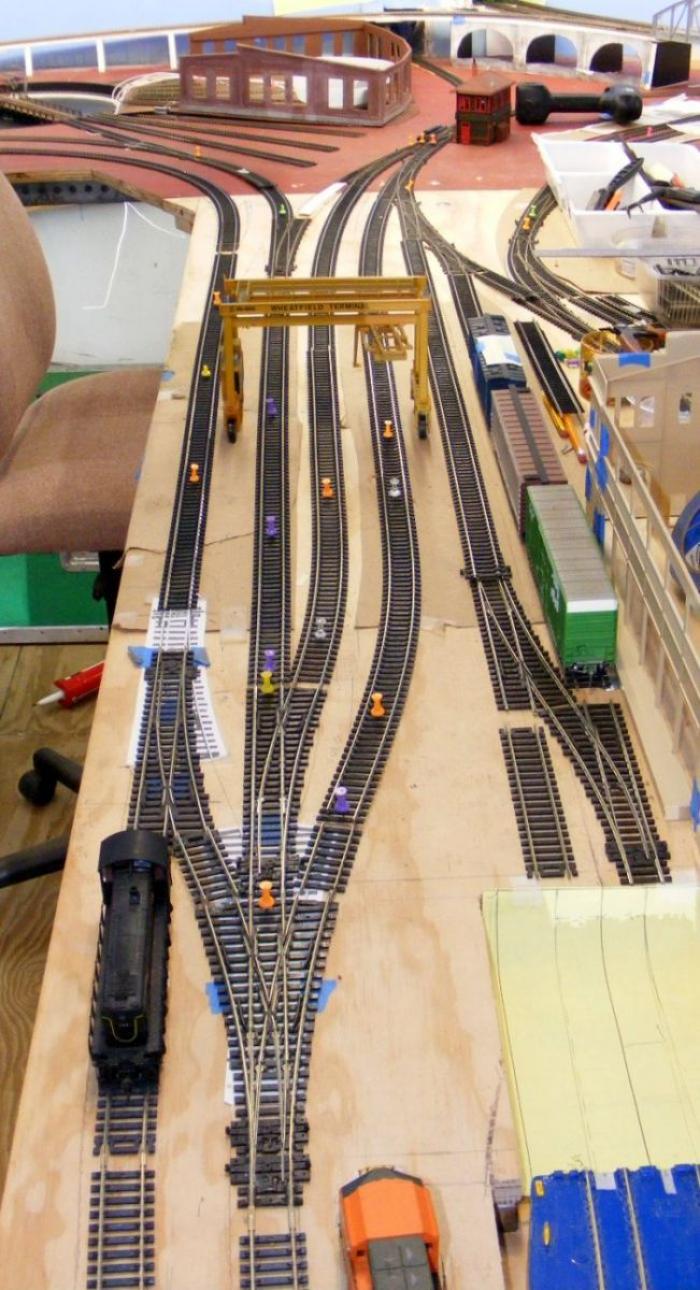
Center Peninsula Track Planning, …..Container Terminal & Port Facility


Actually that metal framework when bolted to together with good strong 3/8 bolts tighten up real well in combination with the 3/4 plywood makes quite a stiff structure.
DSCF5461.JPG

No concerns about swaying,.....its tight.

My one concern was how the cantilevered tip of the upper deck there might eventually bend downward,...just over time rather than due to the load. That carfloat and the pier structure stuck out on the end do not really weight very much. And I built that 'water tray structure' out of the same robust 3/4" plywood that I felt would lend rigidity to the peninsula's tip,...and I glued that tray together along all its edges. However I did NOT glue that tray to the underside of the deck piece, which would have made it even stronger.

It all worked without any horizontal piece underneath.

As a 'just-in case' I have added one more piece of structure that I have not mentioned, nor photographed yet. I'll do the tomorrow.
Okay, here is a couple of photos of my 'just-in-case' support piece,...just a plain old piece of plywood bolted to the lower staging track beam and wedged up under the 'water tray' above.
1591706794009.png


1591706825073.png
 
Last edited:
HAD to get my 2 cents in. Very simple ! 2 things: (1) those 2 tracks that you've bent to fit within the ironing board shape peninsula: So what's stoppin' ya from cutting a sliver of ply and widening the mother, what, 4 inches ? (2) What are you worried bout engines getting trapped at the stub ends ?! Engines don't pull cars in. They push 'em in !! Chek sum YouBoob 1:1 scale switching videos if ya doesn't bell eve me !!
BS.. Though I prefer point to point RRs, for a continual, this is quite a nice plan..And it will be a great RR..
BBS. Employ steam. Who's gonna come and arrest you ? Your hobby/your RR ....
🌵🛤☀🏨🏪
 
Last edited by a moderator:
HAD to get my 2 cents in. Very simple ! 2 things: (1) those 2 tracks that you've bent to fit within the ironing board shape peninsula: So what's stoppin' ya from cutting a sliver of ply and widening the mother, what, 4 inches ? (2) What are you worried bout engines getting trapped at the stub ends ?! Engines don't pull cars in. They push 'em in !! Chek sum YouBoob 1:1 scale switching videos if ya doesn't bell eve me !!
I'm assuming you are suggesting that I NOT have that dbl-slip turnout, but rather 2 separate tracks entering the peninsula??
https://modelrailroadforums.com/forum/index.php?threads/center-peninsula-track-planning-…-container-terminal-port-facility.31911/page-3#post-482957

My aisles are already a bit tight, and the addition of another (subtraction) of another 4+ inches might make things bit more difficult as I age. I just recently needed to add 2 inches to accommodate my pier street terminal building and crate making business.
DSCF5439.JPG

(not the most recent photo, but it shows my need for that extra 2" strip down that right hand edge of the peninsula)


I have also discovered a new siding I will be adding,..
All-purpose Spur
I've been playing around with finishing out this track plan back in the corner that contains my power plant and my coke oven. Bisecting that corner I have a mainline spur that runs down the entire right hand wall and makes a sweeping curve in under the viaduct bridge to a slip switch that feeds the peninsula businesses. At the moment I see spurs off of that track for other sidings including 1) coal for the power plant, 2) coal for the coke plant, 3) coke quenching/extraction track, AND 4) another all-purpose spur. This is a spur that runs right along the backside of the viaduct.
DSCF5475%2C%20all-purpose%20spur.jpg

I had originally thought this spur might be used to bring my large transformer moving cars into for crane installation to the power plant.

But now I see many more uses for this spur. It might be a holding track for many coal and coke related cars servicing this area. It might also be a holding track for a few switcher engine(s) servicing these industries, AND those switcher(s) might also serve to push 'cuts of cars' into the peninsula tracks,...per Dave's suggestion, put the switcher spur on the pusher end of the cut.
https://model-railroad-hobbyist.com/node/38264?page=8#comment-435751


BS.. Though I prefer point to point RRs, for a continual, this is quite a nice plan..And it will be a great RR..
BBS. Employ steam. Who's gonna come and arrest you ? Your hobby/your RR ....

Thanks, I think I am going to enjoy it once up and running. I'm getting tired of all this planning,...re planning.
In case you haven't noticed I am a BIG fan of steam, and my roundhouse will be chocked full....Plus I will be running a lot, including some steamers pulling container trains....ha...ha.
 
Last edited:
What are you worried bout engines getting trapped at the stub ends ?! Engines don't pull cars in. They push 'em in !!
While I believe that push in is the way that Brian should proceed, it is not always the case. Here is the former ATSF (now BNSF) Alliance yard and intermodal facility north of Ft Worth TX in the town of Haslet.
1591727681074.png

Trains pull in from either direction and the engines detach and go for servicing. Resultant reloaded containers can then go back out in either north or south direction. The right most five tracks are the container tracks. Those are all containers and trailers in that parking lot. Of course this is a much bigger facility than anyone of us can model.
 
🌵 WILLIE ..You are right concerning your thru-yard pic above with the main running thru the middle... But the OP has made a stub ended terminus whether or not it's for freight, junk, modal, or passenger..And I don't think there's a runaround escape track either...
 
Albert Einstein was faced with a similar issue when working on his model railroad and he came up with the following formula ,
SY = Ψ(DY - (RE * D)).
A double ended yard minus the available real estate times the cost , multiplied by Ψ ,where Ψ (psi) is the probablity of making it happen equals a single ended reality.

Whack , Whack ,crack.
Excuse me , I have to order a new dead horse beater mine is worn out. Darn things dont last as long as they used to. What do you expect I got it off ebay.
 
Last edited:
GEE, not sure what your humor is about, other than something to do with the adage 'beat a dead horse'. But you can't blame ebay for any misgivings on purchases. That's the dealer/manufacturer's fault... Ebay merely displays things for sale and receives a % of the deal for this service..
 
Wishful Thinking

I've spent a good couple of hours looking back thru this marvelous creation of the Magoun Pier scene over on this other forum
http://www.railroad-line.com/discussion/topic.asp?TOPIC_ID=40790&whichpage=49


201659221410_017.jpg


It makes me wish I had found this discussion, and the many photos while I was still in the preliminary stages of my planning a track plan for my peninsula. I might have tried to devote the entire end of my peninsula to a wharf scene like this.
But when I went out to my layout and took another look, I realized I still did not have enough width on the end of my peninsula to get that scene in,..at least not so with the vessels there...oh well, wishful thinking.
 
I've been in the track laying mode, and quite suddenly decided to go ahead with some of the trackwork in my peninsula area. I thought I had it pretty much worked up with my full size template planning, and an evolution of changes over the past year. I even glued down some of my more complicated turnout joining configurations at the base of the peninsula,...particularly here..


image%28153%29.png


I began to re-look at this situation where I was providing an 'escape segment of track' (arrow above) for steam engines to get back to the 24" radius track feeding the turntable. That escape track was inhibiting the container area/tracks in a major fashion. Do I really need it?


I am thinking of alternatives, but it will mean I need to tear out this considerable work/junction/combination of turnouts I have been taking for granted almost from the beginning of my layout design process. Oh well, so much for the best laid plans
surprise
crying


New Track Plan for Container Tracks
Back on page 1 of this discussion I describe my efforts to provide run-around tracks and tailing tracks for locos that have brought trains into the container tracks. I was trying to provide 'escapes' for both diesel and steam engines that might be pulling those container trains,...and in particular long steam engines which I am very partial to (and yes I realize that steam engines really 'disappeared' prior to containerized freight, but this is MY railroad).

I had wanted (still do) to get the steam engines routed back to steam area (roundtable/roundhouse) and the diesels routed back to the freight car yard. Two loops of tracks, 22”radius and 24” radius, was the best (broadest) I could manage, and the broader 24” one would be used for the steam engines. That created that need for the more complicated turnout combo and that short crossover track.

I have now decided that ANY steam engine bringing a freight train (particularly container train) into the peninsula area must uncouple and choose that left most track (the train engineer's right track), so they can go just beyond that turnout leading to the 'turntable track'. They can then reverse direction and back into that track to the turntable/steam service area.
Switcher engine(s) will then position cars where appropriate.

Original plan


Updated plan


Here you can see the simplified turnout configuration (single one verses 3 turnouts),....and difficult to see, a smoother transitioning 24 radius track to the turntable.
image-20210413084218-3.jpeg

image-20210413084248-4.jpeg


At the other end there is still a tailing track for the diesels (even a pair of them)

image-20210413084449-6.jpeg


Both these engines and the empty container cars can make their way back over to the freight yard via that track along the edge of the deck and the 22” loop at its upper end.
 
Last edited:
One might notice another couple of changes. I have added the third track back into those passing under the container cranes,...probably best expressed by my previous posting,...


I was unsure of exactly how I wanted to space those 2 tracks down in this yard? Then I got to thinking, what if I went ahead and installed 3 tracks, with the option to chose later which combination of 2 tracks I might make use of in the future.? Wait a minute, aren't these tracks under the cranes paved flush with concrete so the tires of the cranes can roll over them? ...Of course, so why not lay down that 3rd container track under the cranes, such that the option exist to use any 2 of the 3 tracks. This might exist in real life as well? I'm pretty sure I want to go forward with this option of 3 container tracks that are buried flush with the concrete paving that the cranes and trucks can drive all around on.


I've made the container yard a bit longer (span distance covered by the cranes) as a result of the less turnouts at the entrance, and shortening of the tailing track.

[/QUOTE]
beiland, is your terminal being made with balsa wood ?
 
oops, I just added this material to another discussion i had started on this peninsula area.....my error


I finally like this final design evolution
yes


image%28155%29.png


image%28157%29.png


...and now I have a track on the other side,...to act as tail track for that other industry that will be on that siding,...and to act as extra waiting track for other cars waiting for either break-freight in warehouse, or eventual loading onto carfloat, etc ( I will have to provide a little extra strip of deck plywood to accommodate this spur)
image%28158%29.png


image%28159%29.png


image%28161%29.png


It was a jig saw puzzle getting that track configuration in there,...thank goodness for Peco turnout design (curved diverging tracks allow for compact track planning).
 
How wi
I will have to provide a little extra strip of deck plywood to accommodate this spur)
[/QUOTE

Beiland, the set up looks awesome !

I loved the old pic of Halifax in one of the threads and it was part of the inspiration for my plans. How wide will this section be now that you are adding that strip for the new spur?
 
24" was the original width,....then I had to add a 2" strip down the side with the terminal building on it,..for both the terminal building and another structure that is going to occupy the spur track up there. So 26" at that point.

Finally I will have to add a strip of 1.75" along side the terminal building to accept that spur track along the side of the building. I figure I will NOT have cars setiing on that spur as they might get knocked off,...but that track offers a operational track.

Here is a pic of when I first experienced the need to make the first addition to the width,..
DSCF5439.JPG
 
Last edited:
New Age Municipal Terminal Buildings

Warehouses are immensely popular even today, but they are used differently than what used to be: today they are either shipping centers (e.g. what Amazon ships from) or distribution centers (where UPS sorts their packages according to destination). Assuming your dock serves multiple over-water destinations, the warehouse would handle re-sorting freight that comes from one ship and needs to be re-distributed for multiple other ships or rail. Stick a "Model-harbor packet service" sign on the warehouse and run some cars from the carfloat to the warehouse. Combine your car-float with some containers "on top" and it seems realistic for me. Even today.
Dark2star
Recently I've been thinking along these same lines,...my municipal terminal building has evolved into more of a centralized warehouse/redistribution center. It can load some small ships that might be delivering to Norfolk or Puerto Rico or Bermuda, etc . Or it can operate in conjunction with the carfloat/barges to deliver to a variety of product to small port cities along both sides of the Chesapeake Bay simultaneously . It can also possibly have some containers loaded on the top by that adjacent dockside crane out back of the terminal building ????

......shades of this image you mentioned Gary
halifax%201930.jpg
 
Very much so and I worked on that steam operated triangular crane barge in the bottom left of the pic. Your layout is looking awesome !
They were getting rid of the trains / rails here as I was growing up
 
I decided to go ahead with gluing up the basic walls and ends of my terminal building today,...getting rid of that multiple blue tape I had used to mock it up. As I sat it back on the layout, my thoughts turned to how the building might be occupied.

I can well imagine at least 3 different offices on the second floor in 3 of the corners of the building,....1) offices for the container yard, 2) offices for the carfloat operation, 3) offices for pier loading of small ships by the big crane out back. And each of those offices on the second floor would have its own individual entrance door down below, plus communication hallways between themselves.


Back
Top