starting over with HO scale


Backdrop with clouds painted is now finished...
 

Attachments

  • 20220717_204519.jpg
    20220717_204519.jpg
    196.3 KB · Views: 117
My benchwork is finished. All is supported by angle steel anchored to wall, except peninsula, which is on legs of black gas pipe with round flanges as feet. framework is steel with wood inserts to screw OSB to. Only two legs to floor makes it alot easier to do wiring underneath, and to clean floor. Got the steel structure idea from Beiland. I have a mechanics seat type creeper for doing wiring. Next step is adding foam sheets on top of OSB.
 

Attachments

  • Finished benchwork.jpg
    Finished benchwork.jpg
    321 KB · Views: 115
Hi. I haven't posted in a long time, not online much, mostly just very busy. Being retired has enabled me to make good progress on my new layout. Track is all worked out and in place. Gratis to AnyRail software...priceless!! Some wiring for DCC is done, but operating trains on DC to test everything. all track joiners on both mainlines are now soldered. Three buildings finished. Will post later on wiring stuff. I came up with a simple system for two lift-out bridges. Will detail that later as well.
 

Attachments

  • track layout left.jpg
    track layout left.jpg
    564.4 KB · Views: 87
  • track layout right.jpg
    track layout right.jpg
    427.8 KB · Views: 90
  • 20221220_125524.jpg
    20221220_125524.jpg
    429.6 KB · Views: 90
  • 20221226_193802.jpg
    20221226_193802.jpg
    631.2 KB · Views: 81
  • nighttime at doors 3.jpg
    nighttime at doors 3.jpg
    425.9 KB · Views: 84
I am back!!! lol,

Let's talk about moving electricity! I want to share a neat way I discovered for doing the wiring under my layout. I was first planning on using T taps but dropped that idea for something a lot easier to use. The item I discovered is called a CirKits SPL-62 Multiple Terminal Block, which is a push-in wiring cable connector. Available from Midwest Model Railroad (https://midwestmodelrr.com/rrcspl-62/). This connector easily mounts to the underside of the layout with two small screws (not included). In this way the connector becomes a support for the wiring at the connection points. This device accepts wire sizes from 28AWG to 12 AWG, and it is easy to disconnect a wire if need be. This is so much better than using T taps since T taps are not offered in one tap covering such a wide range of wire sizes. And neither are suitcase connectors. Also easier than using screw type terminal blocks. And there is no soldering involved! The CirKits SPL-62 handles every wire size that is normally used on a model railroad layout. Each port will accommodate multiple wires which can be twisted together, depending on how many will fit. I have these mounted anywhere I need to tap into the buss circuits, with the buss passing thru. The little levers are simply pulled on to open the port to insert the wires, then let snap back down to secure the wires. Once in awhile the lever may not snap fully into place, but the internal connector does connect firmly.

I am using 14 AWG wire for the Main DCC buses. The KATO wired track terminals I am using are 24 AWG. My turnout buss is 18 AWG and the KATO turnouts come with 24 AWG leads. My layout lighting buss is 18 AWG feeding 28 AWG LED leads. (LED lighting is from Evan Designs, Fort Collins, CO.) Using T tap connectors would not have accommodated these varied wire sizes in one connector. All of my wiring is color coded for ease of identification. The coiled wires in one picture facilitated the in and out movement of the electronics slideout shelf.

For hanging the wiring between the connector blocks I am using plastic plumbing hangers. They are 1/2” plastic hangers with two mounting holes. I only use one screw and that way I can open the hanger from the other end that is not fastened, to insert wires . Very easy, neat, and convenient method of managing the wiring. I painted the underside of my layout white so it would be easier to see the wires and their color coding. My trains are running error free using the DCC system by DigiTrax, and these wiring connectors.
 

Attachments

  • Cirkits connector 1.jpg
    Cirkits connector 1.jpg
    302.1 KB · Views: 63
  • cirkits connectors for slidout shelf.jpg
    cirkits connectors for slidout shelf.jpg
    421.9 KB · Views: 57
  • plumbing clamp as wire hanger 1.jpg
    plumbing clamp as wire hanger 1.jpg
    294.2 KB · Views: 57
  • plumbing clamp as wire hanger 2.jpg
    plumbing clamp as wire hanger 2.jpg
    378.7 KB · Views: 59
  • plumbing clamp package.jpg
    plumbing clamp package.jpg
    479.2 KB · Views: 59
  • slideout electronics shelf with programming track.jpg
    slideout electronics shelf with programming track.jpg
    424.2 KB · Views: 61
  • Slideout shelf stored position.jpg
    Slideout shelf stored position.jpg
    373.1 KB · Views: 65
some pics of other progress with buildings. Added background buildings and a Hershey Chocolate Factory and an Amish farm. I grew up close to Hershey Pennsylvania in Amish country, so a touch of home! All of the buildings have finished interiors and lighting.
 

Attachments

  • 20230625_190446.jpg
    20230625_190446.jpg
    458.1 KB · Views: 60
  • 20230625_184923.jpg
    20230625_184923.jpg
    479.9 KB · Views: 61
  • 20230625_190804.jpg
    20230625_190804.jpg
    355.6 KB · Views: 56
  • Peeking in Chocolaye factory window.jpg
    Peeking in Chocolaye factory window.jpg
    461.4 KB · Views: 55
  • 20230625_185058.jpg
    20230625_185058.jpg
    402.8 KB · Views: 58
  • Farmhouse living room.jpg
    Farmhouse living room.jpg
    156.2 KB · Views: 58
  • Inside office building.jpg
    Inside office building.jpg
    544.7 KB · Views: 57
  • peek into textile factory.jpg
    peek into textile factory.jpg
    372.3 KB · Views: 57
  • Peek into office building.jpg
    Peek into office building.jpg
    196.3 KB · Views: 58
  • Inside Allied Rail Rebuilders shop.jpg
    Inside Allied Rail Rebuilders shop.jpg
    346 KB · Views: 55
Thanks for the compliments!!

If you are using or plan to use KATO track, then you may be interested in this nice controller for KATO turnouts....One of my challenges with space constraints in my layout, which is in a small bedroom, was to have turnout controls mounted on the layout fascia that would not stick out,

Because of this constraint I could not use the turnout controllers made by KATO, they would have stuck out too far when mounted on the fascia. I found a really nice KATO turnout compatible controller made by RPC Electronics, Chesapeake, VA. (rpc-electronics.com/kato.php). They are made in a unit that will control 4 turnouts individually, and a single to control just one turnout. They are almost flush on the fascia. The units mount behind the fascia using standoffs that come with the units. My fascia is 1/8" hardboard.

These are made just for KATO turnouts only, which use momentary reversing DC polarity to throw the turnout different directions. They will not work for turnouts that operate differently. These controllers require input of around 18 volts AC and they convert that to DC to operate the turnouts..

There is a nice face plate that finishes the installation nicely, covering the cutout opening with a professional look. They do not have a faceplate for the single units, so I took the quad faceplate and cut it down to be a single faceplate. In addition to the screw type terminals for the turnout leads, there are power in and power out terminals for the buss connections from one unit to the next. They are available in either front mounted or rear mounted terminal blocks.

To operate, all that is needed is a momentary press of the buttons. Holding the button down would cause an eventual burnout of the turnout.
 

Attachments

  • RPC quad Kato turnout Controller.jpg
    RPC quad Kato turnout Controller.jpg
    24.4 KB · Views: 50
  • RPC Single Turnout Controller.jpg
    RPC Single Turnout Controller.jpg
    108.5 KB · Views: 55
  • Turnout control surface.jpg
    Turnout control surface.jpg
    228 KB · Views: 54
  • Turnout control rear wired.jpg
    Turnout control rear wired.jpg
    395.5 KB · Views: 51
  • Turnout controls quad and single.jpg
    Turnout controls quad and single.jpg
    263.8 KB · Views: 52
  • Turnout controls labeled.jpg
    Turnout controls labeled.jpg
    283.6 KB · Views: 50
Wow, I'm so glad I caught this thread! This is absolutely incredible work! Everything is so detailed and beautiful! Love the aesthetics of the layout table itself as well. Very flowy and natural. Keep up the great work!
 
Let's talk lift-out bridges! My layout requires two lift out bridges just inside the room's door, in order to walk into the human areas within the layout. In researching how others have done lift-out bridges I saw a lot of complexity. One hobbyist even built his bridges to move up ingeniously above head height like an elevator. I decided I did not want my bridges to be using a very complex method of moving out of the way and back into place.

The method I am using is fairly simple, easy to setup, easy to use. I placed the approach tracks in place so they define the bridge placement, I then placed thin strips of metal glued to the OSB which is the platform for the layout that the two 1 inch layers of foam rest on. I then cut wood blocks for the bridge to sit on at each end with the bottom of the blocks having a strip of magnetic sheet glued to them. This magnetic sheet enables the wood blocks to stick to the metal plates to hold bridges in place. The blocks were fabricated to an exacting height that ensures the bridge track matches perfectly to the approach tracks.

The bridges lift out with little effort and when put back into place are easy to line up the tracks. They stay in place and do not move with repeated passing of trains over the bridges. The magnetic attraction between the magnetic sheets and the metal is just right to keep bridges in place while also making it easy to lift out the bridges. I built two shelves to place the bridges on when removed. The electrical connections are made with short wires that plug into a terminal block from KATO with quick release modular plugs. I had to modify the internal connections inside the terminal block to have two separate circuits since each bridge is on main line loops that are powered separately on the DCC system as power districts.Since the bridge tracks do not actually touch the mainline tracks at one end, they provide the perfect break that ensures there is not a continuous loop in the DCC circuitry, which is required with DCC, in the information I have.

I finished things off at each end of where the bridges sit, by using flexible concrete walls from Walther's (Chooch brand), and painting these walls, and wood blocks that are glued to the bridges, a concrete color. A friend suggested that I should consider a removable flat piece of sheathing to span the area under the bridges. This would be finished off to look like a river that the bridges are passing over.
 

Attachments

  • liftout bridge in place 4.jpg
    liftout bridge in place 4.jpg
    457 KB · Views: 56
  • liftout bridge in place 5.jpg
    liftout bridge in place 5.jpg
    402.7 KB · Views: 54
  • liftout bridge in place 1.jpg
    liftout bridge in place 1.jpg
    289.9 KB · Views: 51
  • liftout bridge magnetic attachment 1.jpg
    liftout bridge magnetic attachment 1.jpg
    262.3 KB · Views: 56
  • liftout bridge magnetic attachment 2.jpg
    liftout bridge magnetic attachment 2.jpg
    361.8 KB · Views: 53
  • liftout bridge retaing walls 1.jpg
    liftout bridge retaing walls 1.jpg
    369 KB · Views: 55
  • liftout bridge retaing walls 2.jpg
    liftout bridge retaing walls 2.jpg
    268.1 KB · Views: 50
  • liftout bridge track alignment 1.jpg
    liftout bridge track alignment 1.jpg
    430.2 KB · Views: 52
I have finished my first scene on my new HO layout. It is an Amish Farm, in a corner of my layout which I had no other plans for. I live in Colorado but I grew up in Lancaster County, Pennsylvania, Amish and Mennonite country. So even though my layout depicts (with lots of liberties) the area around Castle Rock, Colorado. I wanted to incorporate some things from my family home area (where most of my family and relatives live) into my layout. There are now around 5 or 6 small Amish communities in Colorado. Now if I could just figure out a way to incorporate a covered bridge! If you don't know alot about the Amish Culture, I recommend you watch this video... “The Amish: Back Roads to Heaven”, full movie by Burton Buller
 

Attachments

  • Stoltzfus Amish Farm view.jpg
    Stoltzfus Amish Farm view.jpg
    270.9 KB · Views: 34
  • Amish farm, Stoltzfus farmhouse.jpg
    Amish farm, Stoltzfus farmhouse.jpg
    563.6 KB · Views: 34
  • Amish farm garden & wash day.jpg
    Amish farm garden & wash day.jpg
    435 KB · Views: 36
  • Amish farm barn with Hex signs.jpg
    Amish farm barn with Hex signs.jpg
    470.7 KB · Views: 36
  • Amish Farm milking shed.jpg
    Amish Farm milking shed.jpg
    426.2 KB · Views: 33
  • Amish farm pumpkin patch & corn bin.jpg
    Amish farm pumpkin patch & corn bin.jpg
    527 KB · Views: 32
  • Amish farm cornfield & plowing.jpg
    Amish farm cornfield & plowing.jpg
    561.3 KB · Views: 36
  • Stoltzfus family farm back story.pdf
    58 KB · Views: 31
  • peek into farmhouse 1.jpg
    peek into farmhouse 1.jpg
    385.9 KB · Views: 33
I have finished my first scene on my new HO layout. It is an Amish Farm, in a corner of my layout which I had no other plans for. I live in Colorado but I grew up in Lancaster County, Pennsylvania, Amish and Mennonite country. So even though my layout depicts (with lots of liberties) the area around Castle Rock, Colorado. I wanted to incorporate some things from my family home area (where most of my family and relatives live) into my layout. There are now around 5 or 6 small Amish communities in Colorado. Now if I could just figure out a way to incorporate a covered bridge! If you don't know alot about the Amish Culture, I recommend you watch this video... “The Amish: Back Roads to Heaven”, full movie by Burton Buller
An interesting subject to model, don't think I've seen anyone model this subject before, great work too.
 
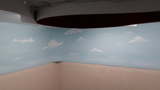
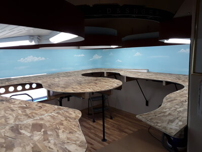
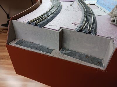
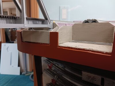
Finally getting some time to submit anew post. This one is about the mountain I have added to my layout. The mountain is in a corner of my layout, kinda like an anchor! Theidea is for the flat landscape and parallel tracks to lead the eye tothe mountain. Two mainline tracks go through tunnels. Both mainlinesenter the tunnels on the same level but one line climbs a gradeinside tunnel so at the other end they are at different levels. Infront of the mountain will be the Champion Packing Plant by Walthers.

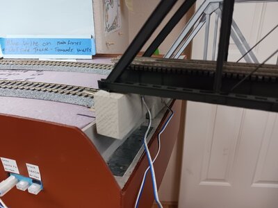
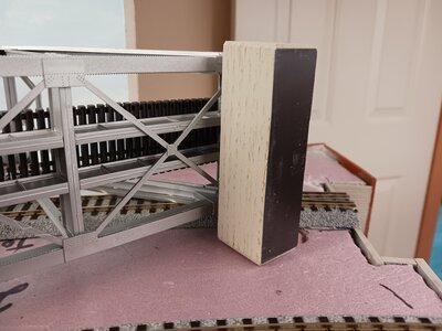
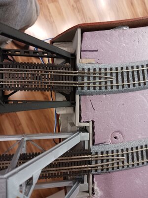
I started with making the tunnels,using a sheet of one inch foam for the ceiling. I had some flexible3/8” foam laying around which I used for the walls of the tunnels. I used some techniques for the tunnels I saw on a YouTube video doneby a young guy in South Africa named Gerben. He has some videos onYouTube under “ThecreativemodellerHO. His method of lining thetunnels with crumpled craft paper makes for realistic tunnel rockwalls. I used spray paint to color the tunnel walls.

I then built the mountain using layersof scrap pieces of 1 inch thick foam, held in place with constructionadhesive. I then covered the foam with home-made sculptamold. Iused Gerben's method of making sculptamold from egg cartons processedthrough a blender to shred them, and then I mixed it with Easy Sand90 minute drywall joint compound available at Home Depot and Lowes. This works well, it gives a 90 minute working time so I don't have torush when using it, plenty of time to get the terrain shape justright before it sets up.

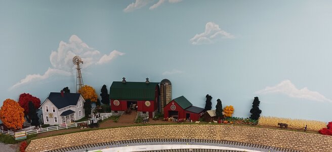
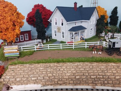
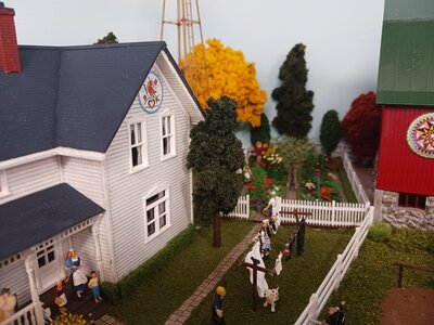
The mountain design is taken fromCastle Rock in Colorado. I also use Castle Rock as the name of thelittle town on my layout. My two mainlines are the Denver & RioGrande Western, and the Atchison, Topeka and Santa Fe. HistoricallyCastle Rock Colorado was served by both of these railroads, thus thereason for the Castle Rock town and the Castle Rock mountain on mylayout. Of course I have taken great liberties with both so neitheris accurately modeled correct to reality. Two things that areaccurate is the American flag flying 24/7 and lit at night, and ahiking trail to the top of Castle Rock. The landscape includes tallpines, some different varieties of oak, aspen, grasses, briars, andlow evergreen scrub. It is fall season so the oaks and aspen areshowing fall colors.

I built the top of the mountain using aone gallon plastic paint container cut down to the right height. Ithen glued flexible rock castings on this container, leaving the endsfanning out so they meet the backdrop at the right angles. I alsoglued plaster rock castings on the top and then landscaped the top. Afew trees on top have been killed by lightning strikes. In additionto the flags, there are radio and tv broadcast towers.

1  Building the tunnels.jpg2  mountain construction.jpg3  sculptamold added.jpg4  Sculptamold finished and painted.jpg5  Inside tunnel.jpg6  Full mountain pic.jpg7  Top of Castle Rock mtn.jpg8  Lighted flags.jpg9  Hikers 1.jpg10  Hikers 2.jpg


Back
Top