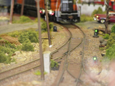
Tomar Dwarf Signals


D&J RailRoad

Professor of HO
Finally getting around to installing some Dwarf signals on the modular yard throat.
I had quite a few of them left over from the previous layout. I bought a few more at Main Line Hobbies to be sure I had enough because I want to install a few on the empire in the basement too.
OK, 12VDC wall wart, a handful of 1.5K Ohm and 390 ohm resistors so the LEDs don't burn out. They don't show a closed circuit with a VOHM meter so can only test with a resister soldered to a 9volt battery. Didn't bother with the test because they were working when I salvaged them. Installed em next to the tracks and let em dry over night. Today, mounted the wall wart on the module power strip that powered the Digitrax DS64s then rounted the + and - wires to the Tortoise machine contacts. Continued the wire run to the dwarf,,,,,,,,, no light. Hmmmm. Checked for voltage at the two leads, 12VDC. Make solder connection the dwarf leads again. No light. Sumpin is wrong. I did the 9volt battery test on the dwarf signal, red light comes up. reconnect to the wall wart, no light.
Puzzled.

This picture is the connection from the wall wart.

20211028_174009.jpg


Dwarf signals on the road bed. Engineer reads the one to the right of the track he is on.
20211028_174021.jpg
 
Huummm, sumting rong fo chur!
Are you positive the wall wart is working as advertised, or that the resistors?
Try one without the resistor.
 
Yep, tried it without the resistor by mistake and "poof". That dwarf is dead now.
I discovered I had a 12 VAC wall wart. It happened when I was sorting them out in the box o stuff in the basement. I read the lable that said 12VAC but put it in the DC pile.
OK, figured that problem out and installed a real 6VDC wall wart instead. Tested the Dwarf with the 9V battery, good. Ran the wires from the wall wart to the dwarf ground wire and the other one through the Tortoise machine contacts. Tested the leads for voltage, yep. Touched them to the dwarf red lead and a quick flash. Dang, forgot to put the resistor in series. Pulled that dwarf out of the module and moved on to the next dwarf to the left in the picture. Ran the wires, installed the resistor, nothing. Geezo criminey, give me a break. OK, lets just reverse the polarity of the input from the wall wart. Dwarf lights up. Hmmmm, the polarity is opposite of what it says.
OK, had enough frustration for one day. Will wire the other one tomorrow. I ran out of the 390 ohm resistors so ordered a pack of em. Should be here tomorrow so I can get the top green light operating too.
Camera angle makes the dwarf on the left look like its almost falling over. It's actually standing straight up.
I used Gorrilla glue to install them. Just a tiny drop on the bottom side of the dwarf then press em into the ballast. Gorrilla glue expands exponentially. There is still some showing around the base of each signal and that is after I trimmed quite a bit away after it dried.
The one is missing on the right because of the accidental connection without a resistor.


20211028_185058.jpg
 
Of Course, you had to grab the only 12VAC from the box of 50?
WOW - You must have been pulling out what hair you have left - no wonder - is this a regular occurrence?
On a more serious side -- can the blubs be replaced in the "burned out" Little SIGNALS" ??
 
Got both colors working with the push button activators for the turnouts.


The wire leads from the dwarf signals were so fine, I could solder them then cover them with the cardboard to protect them. They're near the end of the module where the clamps go to secure it to the next module.
For orientation purposes, I have the module standing on its edge on my kitchen counter top.

20211029_163327.jpg


The switching is done with the contacts provided on the Tortoise machine.
20211029_163359.jpg
 
I installed over twenty of the Tomar Green over Red LED dwarf signals on my layout. Don't forget for a long LED life, that Tomar recommends the following for resistors for the LED's...

The instruction sheet that comes with the dwarf signal suggests a 1500 ohms, 1/2 watt, resistor for the red LED and a 390 ohms, 1/2 watt, resistor for the green LED.

Greg

IMG_0146.JPG
Some of the signals on the CM&N Railroad. I really should have the signals on either side of the tracks facing in opposite directions, but the ones that are installed should be in the direction that faces the operators.-Greg
 
Last edited:
wiring diagram is in my head.
I'm in compliance with the Tomar recommendations, 1.5Kohm and 470ohm instead of the 390 on the green from a 6VDC wall wart. Still looks just as good.
 
Which Gorilla glue did you use? It sounds like it does the trick to secure the dwarf signals. I've had problems with my method(s) to secure my dwarf signals to keep them upright and straight.

Greg


Back
Top